29
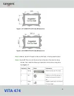
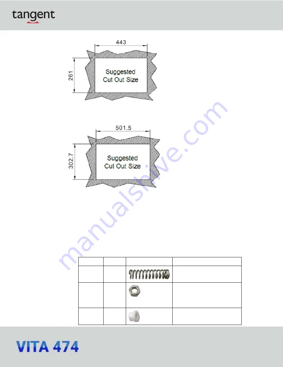
Figure 3-5: 19-INCH VITA 474 Cutout Dimensions
Figure 3-6: 22-INCH VITA 474 Cutout Dimensions
Step 3:
Slide the panel PC through the hole until the frame is flush against the panel.
Step 4:
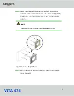
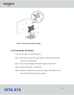
Insert a M5*50 screw into the screw hole on the side of the panel mounting
bracket. Then, install the following components onto the screw in sequence.
See
Figure 3-7
.
Sequence Item
Photo
Instruction
1
Spring
Install a spring onto the screw.
2
Nut
Tighten a nut until the spring is
compressed enough for plastic
cap.
3
Plastic
cap
Tighten a plastic cap onto the end
of screw thread.
Summary of Contents for VITA 474
Page 1: ...tan g ent USER MANUAL...
Page 8: ...8 Chapter 1 Introduction...
Page 20: ...20 Unpacking Chapter 2...
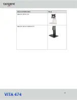
Page 23: ...23 Item and Part Number Image Stand for VESA 100 Stand for VESA 75 VESA 100...
Page 24: ...24 Installation Chapter 3...
Page 34: ...34 BIOS Setup Chapter 4...
Page 70: ...70 Appendix A Regulatory Compliance...
Page 74: ...74 Appendix B Safety Precautions...
Page 80: ...80 Appendix C Watchdog Timer...

