background image

61 


4.4.1.2  Memory Configuration 


Use the 

Memory Configuration 

submenu (

BIOS Menu 18

) to display the memory 

information. 


Aptio Setup Utility 

 Copyright (C) 2017 American Megatrends, Inc. 


Chipset


Memory Information 


Total Memory 
DIMM1 
DIMM2 

4096 MB 
Not Present 
4096 MB 


---------------------


→

: Select Screen


: Select Item 

EnterSelect


+ -   Change Opt. 
F1  General Help


F2  Previous Values


F3  Optimized Defaults 
F4  Save & Exit


ESC  Exit


Version 2.17.1255. Copyright (C) 2017 American Megatrends, Inc. 

BIOS Menu 18: Memory Configuration 


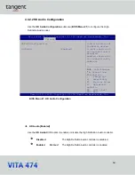
4.4.2 PCH-IO Configuration 


Use the 

PCH-IO Configuration 

menu (

BIOS Menu 19

) to configure the PCH-IO chipset. 


Aptio Setup Utility 

 Copyright (C) 2017 American Megatrends, Inc. 


Chipset


Auto Power Button Status 

[Disable (ATX)] 

Restore AC Power Loss 

[Last State]


>


PCI Express Configuration


>


HD Audio Configuration


Select AC power state 
when power is re-applied 
after a power failure.


---------------------


→

: Select Screen


: Select Item 

EnterSelect


+ -   Change Opt. 
F1  General Help


F2  Previous Values 
F3  Optimized Defaults 
F4  Save & Exit


ESC  Exit


Version 2.17.1255. Copyright (C) 2017 American Megatrends, Inc. 

BIOS Menu 19: PCH-IO Configuration 

Summary of Contents for VITA 474

Page 1: ...tan g ent USER MANUAL...

Page 2: ...hat exceeds the maximum operating temperature described in the user manual Warning Use only the adapter and power cord approved for this system Use of another type of adapter may risk fire or explosio...

Page 3: ...f the use or inability to use the product or documentation even if advised of the possibility of such damages This document contains proprietary information protected by copyright All rights are reser...

Page 4: ...essages should be heeded to help reduce the chance of losing data or damaging the product NOTE These messages inform the reader of essential but non critical information These messages should be read...

Page 5: ...18 1 7 3 22 inch VITA 474 Dimensions 19 2 UNPACKING 20 2 1 UNPACKING 21 2 2 PACKING LIST 21 2 3 OPTIONAL ITEMS 22 3 INSTALLATION 24 3 1 MOUNTING THE SYSTEM 25 3 1 1 Wall Mounting 25 3 1 2 Panel Mount...

Page 6: ...ion 47 4 3 5 1 Legacy Console Redirection Settings 48 4 3 5 2 Console Redirection Settings 49 4 3 6 CPU Configuration 51 4 3 7 SATA Configuration 53 4 3 8 USB Configuration 55 4 4 CHIPSET 56 4 4 1 Sys...

Page 7: ...7 B 1 3 Product Disposal 77 B 2 MAINTENANCE AND CLEANING PRECAUTIONS 78 B 2 1 Maintenance and Cleaning 78 B 2 2 Cleaning Tools 78 C WATCHDOG TIMER 80 D HAZARDOUS MATERIALS DISCLOSURE 83...

Page 8: ...8 Chapter 1 Introduction...

Page 9: ...e i5 6300U Celeron 3955U is a System on Chip SoC that ensures optimal memory graphics and peripheral I O support The system comes with 4 0 GB of DDR4 SO DIMM memory ensuring smooth data throughputs wi...

Page 10: ...em max 32 GB Anti glare anti UV projected capacitive type touchscreen Wi Fi 802 11a b g n ac high speed wireless Two PCIe GbE RJ 45 connectors Two internal speakers Four USB 3 0 ports One RS 232 422 4...

Page 11: ...Figure 1 2 Figure 1 2 Front View There is a power LED indicator located on the front panel The status descriptions of the power LED indicator are listed below Off power cord not attached or power sup...

Page 12: ...ttom Panel The bottom panel of the VITA 474 has the following connectors and switches Figure 1 3 15 INCH VITA 474 Bottom Panel Figure 1 4 19 INCH VITA 474 Bottom Panel Figure 1 5 22 INCH VITA 474 Bott...

Page 13: ...s two speakers and retention screw holes that support VESA mounting The rear panel also has several retention screw holes for installing the optional barcode scanner and magnetic stripe card reader Fi...

Page 14: ...160 170 160 170 160 Backlight MTBF 50 000 hrs 30 000 hrs 30 000 hrs Backlight LED LED LED Touchscreen Anti glare Anti UV projected capacitive Anti glare Anti UV projected capacitive Anti glare Anti UV...

Page 15: ...100 mm x 100 mm Mounting Panel wall rack stand or arm mounting Front Panel Color Black C Net Gross Weight 4 5 kg 6 5 kg 7 3 kg 10 kg 7 8 kg 11 2 kg Dimensions W x H x D mm 396 x 250 x 64 472 x 292 x...

Page 16: ...422 485 serial port DB 9 connector 1 x RS 232 serial port DB 9 connector 2 x GbE LAN RJ 45 connector 4 x USB 3 0 connectors 1 x HDMI output connector 1 x Power switch 1 x AT ATX switch 1 x Reset butt...

Page 17: ...17 1 7 Dimensions The following sections list the dimensions of each model 1 7 1 15 INCH VITA 474 Dimensions The 15 INCH VITA 474 dimensions are shown below Figure 1 7 15 INCH VITA 474 Dimensions mm...

Page 18: ...18 1 7 2 19 INCH VITA 474 Dimensions The 19 INCH VITA 474 dimensions are shown below Figure 1 8 19 INCH VITA 474 Dimensions mm...

Page 19: ...19 1 7 3 22 INCH VITA 474 Dimensions The 22 INCH VITA 474 dimensions are shown below Figure 1 9 22 INCH VITA 474 Dimensions mm...

Page 20: ...20 Unpacking Chapter 2...

Page 21: ...Step 1 Carefully cut the tape sealing the box Only cut deep enough to break the tape Step 2 Open the outside box Step 3 Carefully cut the tape sealing the box Only cut deep enough to break the tape S...

Page 22: ...m Image 1 VITA 474 panel PC 1 96 W power adapter 1 Power cord 4 Screws M4 6 for VESA mounting 4 Screws M3 4 for HDD installation 2 3 Optional Items The following are optional components which may be s...

Page 23: ...23 Item and Part Number Image Stand for VESA 100 Stand for VESA 75 VESA 100...

Page 24: ...24 Installation Chapter 3...

Page 25: ...tep 1 Select the location on the wall for the wall mounting bracket Step 2 Carefully mark the locations of the four screw holes in the bracket on the wall Step 3 Drill four pilot holes at the marked l...

Page 26: ...bezel panel PC and tighten until the screw shank is secured against the rear panel Figure 3 2 WARNING Please use the M4 screws provided in the wall mount kit for the rear panel If the screw is missing...

Page 27: ...in the slotted holes Figure 3 2 Ensure that all four of the mounting screws fit snugly into their respective slotted holes NOTE In the diagram below the bracket is already installed on the wall Figure...

Page 28: ...lat bezel panel PC into a panel please follow the steps below Step 1 Select the position on the panel to mount the panel PC Step 2 Cut out a section corresponding to the size shown below The size must...

Page 29: ...Step 4 Insert a M5 50 screw into the screw hole on the side of the panel mounting bracket Then install the following components onto the screw in sequence See Figure 3 7 Sequence Item Photo Instructio...

Page 30: ...7 Panel Mounting Kit Installation Step 6 Align the panel mounting bracket screw holes with the VESA mounting holes on the rear of the panel PC Step 7 Secure the two panel mounting brackets to the rea...

Page 31: ...3 1 3 Stand Mounting To mount the VITA 474 using the stand mounting kit please follow the steps below Step 1 Locate the screw holes on the rear of the VITA 474 This is where the bracket will be attach...

Page 32: ...ower cord to the power adapter Connect the other end of the power cord to a power source Step 2 Connect the power adapter to the power connector of the VITA 474 Step 3 Locate the power button on the I...

Page 33: ...stem 3 3 Reset the System The reset button enables user to reboot the system when the system is turned on The reset button location is shown in Figure 3 11 Press the reset button to reboot the system...

Page 34: ...34 BIOS Setup Chapter 4...

Page 35: ...E or F2 key as soon as the system is turned on or 2 Press the DELETE orF2 key when the Press Del to enter SETUP message appears on the screen If the message disappears before the DELETE or F2 key is p...

Page 36: ...p Window press ESC or the F1 key again 4 1 4 Unable to Reboot after Configuration Changes If the computer cannot boot after changes to the system configuration is made CMOS defaults Use the jumper des...

Page 37: ...essor Information Name SkyLake Brand String Intel R Core TM i5 6300U CPU 2 40GHz Frequency 2300 MHz Processor ID 406E3 Stepping D0 K0 Number of Processors 2Core s 4Thread s Microcode Revision BA GT In...

Page 38: ...e xx xx xx Use the System Time option to set the system time Manually enter the hours minutes and seconds 4 3 Advanced Use the Advanced menu BIOS Menu 2 to configure the CPU and peripheral devices thr...

Page 39: ...on 2 17 1255 Copyright C 2017 American Megatrends Inc BIOS Menu 2 Advanced 4 3 1 ACPI Settings The ACPI Settings menu BIOS Menu 3 configures the Advanced Configuration and Power Interface ACPI options...

Page 40: ...IO Configuration menu BIOS Menu 4 to set or change the configurations for the serial ports Aptio Setup Utility Copyright C 2017 American Megatrends Inc Advanced F81866 Super IO Configuration Super IO...

Page 41: ...timized Defaults F4 Save ESC Exit Version 2 17 1255 Copyright C 2017 American Megatrends Inc BIOS Menu 5 Serial Port n Configuration 4 3 2 1 1 Serial Port 1 Configuration Serial Port Enabled Use the S...

Page 42: ...ss is IRQ3 4 5 6 7 9 10 11 12 Device Mode RS232 Use the Device Mode option to select the Serial Port 3 signaling mode RS422 Serial Port 3 signaling mode is RS 422 RS232 DEFAULT Serial Port 3 signaling...

Page 43: ...RQ3 4 5 6 7 9 10 11 12 4 3 2 1 3 Serial Port 3 Configuration Serial Port Enabled Use the Serial Port option to enable or disable the serial port Disabled Disable the serial port Enabled DEFAULT Enable...

Page 44: ...l port IO port address and interrupt address Auto DEFAULT The serial port IO port address and interrupt address are automatically detected IO 2E8h IRQ 11 Serial Port I O port address is 2E8h and the i...

Page 45: ...CPU_CORE 0 880 V Select Screen Select Item EnterSelect Change Opt F1 General Help 5V 5 045 V 12V 12 056 V 3 3V 3 296 V 3 3VSB 3 328 V 5VSB 5 016 V F2 Previous Values F3 Optimized Defaults F4 Save Exit...

Page 46: ...3 Optimized Defaults F4 Save ESC Exit Version 2 17 1255 Copyright C 2017 American Megatrends Inc BIOS Menu 7 RTC Wake Settings Wake system with Fixed Time Disabled Use the Wake system with Fixed Time...

Page 47: ...s COM2 Console Redirection Disabled Console Redirection Settings COM3 Console Redirection Disabled Console Redirection Settings COM4 Console Redirection Disabled Console Redirection Settings Legacy Co...

Page 48: ...ion of Legacy OS and Legacy OPROM Messages Select Screen Select Item EnterSelect F1 General Help F2 Previous Values F3 Optimized Defaults F4 Save ESC Exit Version 2 17 1255 Copyright C 2017 American M...

Page 49: ...char set VT100 ASCII char set VT100 Extends VT100 to support color function keys etc VT UTF8 Uses UTF8 encoding to map Unicode chars onto 1 or more bytes Select Screen Select Item EnterSelect F1 Gene...

Page 50: ...ta Bits 8 Use the Data Bits option to specify the number of data bits 7 Sets the data bits at 7 8 DEFAULT Sets the data bits at 8 Parity None Use the Parity option to specify the parity bit that can b...

Page 51: ...eed 2300 MHz Processor Cores 2 Hyper Threading Technology Supported Intel VT x Technology Supported Intel SMX Technology Supported 64 bit Supported EIST Technology Supported L1 Data Cache 32 KB x 2 L1...

Page 52: ...e one core in the processor package Intel Virtualization Technology Disabled Use the Intel Virtualization Technology option to enable or disable virtualization on the system When combined with third p...

Page 53: ...n Megatrends Inc Advanced STAT Controller s Enabled SATA Mode Selection AHCI SATA1 Empty Hot Plug Disabled mSATA M_PCIE1 Empty Hot Plug Disabled Enable or disable SATA Device Select Screen Select Item...

Page 54: ...uration utility ensure to set the Option ROM Messages BIOS option in the Boot menu to Force BIOS This is to allow the Press CTRL I to enter Configuration Utility message to appear during POST Press Ct...

Page 55: ...Optimized Defaults F4 Save ESC Exit Version 2 17 1255 Copyright C 2017 American Megatrends Inc BIOS Menu 13 USB Configuration USB Devices The USB Devices Enabled field lists the USB devices that are e...

Page 56: ...yright C 2017 American Megatrends Inc Main Advanced Chipset Security Boot Save Exit System Agent SA Configuration PCH IO Configuration System Agent SA Parameters Select Screen Select Item EnterSelect...

Page 57: ...T d capability Graphics Configuration Memory Configuration Select Screen Select Item EnterSelect Change Opt F1 General Help F2 Previous Values F3 Optimized Defaults F4 Save Exit ESC Exit Version 2 17...

Page 58: ...ct Screen Select Item EnterSelect Change Opt F1 General Help F2 Previous Values F3 Optimized Defaults F4 Save Exit ESC Exit Version 2 17 1255 Copyright C 2017 American Megatrends Inc BIOS Menu 16 Grap...

Page 59: ...located to the integrated graphics processor when the system boots The system memory allocated can then only be used as graphics memory and is no longer available to applications or the operating syst...

Page 60: ...ernal graphics present Secondary boot display selection will appear based on your selection VGA modes will be supported only on primary display Select Screen Select Item EnterSelect Change Opt F1 Gene...

Page 61: ...gatrends Inc BIOS Menu 18 Memory Configuration 4 4 2 PCH IO Configuration Use the PCH IO Configuration menu BIOS Menu 19 to configure the PCH IO chipset Aptio Setup Utility Copyright C 2017 American M...

Page 62: ...Express Configuration submenu BIOS Menu 20 to configure the PCI Express slots Aptio Setup Utility Copyright C 2017 American Megatrends Inc Chipset PCI Express Configuration M_PCIE_1 Slot Settings M2_M...

Page 63: ...disable detecting if a non compliance PCI Express device is connected to the PCI Express slot Disabled DEFAULT Disables to detect if a non compliance PCI Express device is connected to the PCI Expres...

Page 64: ...onally disabled Enabled Azalia will be unconditionally Enabled Select Screen Select Item EnterSelect Change Opt F1 General Help F2 Previous Values F3 Optimized Defaults F4 Save Exit ESC Exit Version 2...

Page 65: ...r on password and must be entered to boot or enter Setup In Setup the User will have Administrator rights The password length must be Minimum length 3 Maximum length 20 Administrator Password User Pas...

Page 66: ...C 2017 American Megatrends Inc BIOS Menu 23 Boot Bootup NumLock State On Use the Bootup NumLock State BIOS option to specify if the number lock setting must be modified during boot up On DEFAULT Allo...

Page 67: ...d Launch PXE OpROM Disabled Use the Launch PXE OpROM option to enable or disable boot option for legacy network devices Disabled DEFAULT Ignore all PXE Option ROMs Enabled Load PXE Option ROMs Option...

Page 68: ...General Help F2 Previous Values F3 Optimized Defaults F4 Save ESC Exit Version 2 17 1255 Copyright C 2017 American Megatrends Inc BIOS Menu 24 Exit Save Changes and Reset Use the Save Changes and Rese...

Page 69: ...ser Defaults Use the Save as User Defaults option to save the changes done so far as user defaults Restore User Defaults Use the Restore User Defaults option to restore the user defaults to all the se...

Page 70: ...70 Appendix A Regulatory Compliance...

Page 71: ...e user modifies and or install other devices in the equipment the CE conformity declaration may no longer apply If this equipment has telecommunications functionality it also complies with the require...

Page 72: ...s own expense Federal Communication Commission Interference Statement This equipment has been assembled with components that comply with the limits for a Class B digital device pursuant to Part 15 of...

Page 73: ...y Use Period EFUP This is an estimate of the number of years that these substances would not leak out or undergo abrupt change This product may contain replaceable sub assemblies components which have...

Page 74: ...74 Appendix B Safety Precautions...

Page 75: ...ully disengage the power to the unit please disconnect the power cord from the AC outlet Refer servicing to qualified service personnel The AC outlet shall be readily available and accessible Do not a...

Page 76: ...hat whenever the VITA 474 is opened and any of the electrical components are handled the following anti static precautions are strictly adhered to Wear an anti static wristband Wearing a simple anti s...

Page 77: ...as electronic device in terms of the European Directive 2012 19 EU WEEE and must not be disposed of as domestic garbage EU wide legislation as implemented in each Member State requires that waste elec...

Page 78: ...ce of soft dry cloth or a slightly moistened cloth The interior of the device does not require cleaning Keep fluids awayfrom the device interior Be cautious of all small removable components when vacu...

Page 79: ...pecifically designed for computers isone of the best methods of cleaning the device Dust and dirt can restrict the airflow in the device and cause its circuitry to corrode Cotton swabs Cotton swaps mo...

Page 80: ...80 Appendix C Watchdog Timer...

Page 81: ...1 AH 6FH Sub function Call sub function 2 to set the time out period of Watchdog Timer first If the time out value is not zero the Watchdog Timer starts counting down When the timer value reaches zer...

Page 82: ...ed the system will automatically restart after the Timer has finished its countdown EXAMPLE PROGRAM INITIAL TIMER PERIOD COUNTER W_LOOP MOV MOV AX 6F02H BL 30 setting the time out value time out value...

Page 83: ...83 Appendix D Hazardous Materials Disclosure...
Page 84: ...nents will be separately marked Please refer to the following table Part Name Toxic or Hazardous Substances and Elements Lead Pb Mercury Hg Cadmium Cd Hexavalent Chromium CR VI Polybrominated Biphenyl...

Reviews: