background image

GB

GB

Table of Contents

••••••••••••••••••••••••••••••••••••••••••••••••••••••••••••••••••••••••••••••••••••••

3

─────────────────────────────

Applications

••••••••••••••••••••••••••••••••••••••••••••••••••••••••••••••••••••••••••••••••••••••••••••••••

4

─────────────────────────────

Safety Notes

••••••••••••••••••••••••••••••••••••••••••••••••••••••••••••••••••••••••••••••••••••••••••••••••

4

Caution Symbols

••••••••••••••••••••••••••••••••••••••••••••••••••••••••••••••••••••••••••••••••••••••••

4

Warning

•••••••••••••••••••••••••••••••••••••••••••••••••••••••••••••••••••••••••••••••••••••••••••••••••

4

Caution

••••••••••••••••••••••••••••••••••••••••••••••••••••••••••••••••••••••••••••••••••••••••••••••••••••

4

[Maintenance]

•••••••••••••••••••••••••••••••••••••••••••••••••••••••••••••••••••••••••••••••••••••••

5

[Instructions for Measurement]

•••••••••••••••••••••••••••••••••••••••••••••••••••••••

5

<Usage Conditions>

•••••••••••••••••••••••••••••••••••••••••••••••••••••••••••••••••••••••••••••••••

5

<Storage Conditions>

••••••••••••••••••••••••••••••••••••••••••••••••••••••••••••••••••••••••••••••

5

<Power Source>

•••••••••••••••••••••••••••••••••••••••••••••••••••••••••••••••••••••••••••••••••••••••••

5

─────────────────────────────

1. Product Assembly and Components

•••••••••••••••••••••••••••••••••••••••••••••••••••

6

Product Components

••••••••••••••••••••••••••••••••••••••••••••••••••••••••••••••••••••••••••

6

Control Panel

•••••••••••••••••••••••••••••••••••••••••••••••••••••••••••••••••••••••••••••••••••••••••

7

Symbols and their Meanings

•••••••••••••••••••••••••••••••••••••••••••••••••••••••••••

7

2. Preparation for Use

••••••••••••••••••••••••••••••••••••••••••••••••••••••••••••••••••••••••••••••••••

8

Level Adjustment

•••••••••••••••••••••••••••••••••••••••••••••••••••••••••••••••••••••••••••••••••

8

Installation of the Equipment

••••••••••••••••••••••••••••••••••••••••••••••••••••••••••

8

Prepare Power Source

••••••••••••••••••••••••••••••••••••••••••••••••••••••••••••••••••••••••

9

3. Operating Instructions

•••••••••••••••••••••••••••••••••••••••••••••••••••••••••••••••••••••••••••

10

Measurement Procedures

•••••••••••••••••••••••••••••••••••••••••••••••••••••••••••••••

10

Automatic Power Off

•••••••••••••••••••••••••••••••••••••••••••••••••••••••••••••••••••••••

10

4. Troubleshooting

•••••••••••••••••••••••••••••••••••••••••••••••••••••••••••••••••••••••••••••••••••••••

11

Possible problems

••••••••••••••••••••••••••••••••••••••••••••••••••••••••••••••••••••••••••••••

11

─────────────────────────────

Specifications

••••••••••••••••••••••••••••••••••••••••••••••••••••••••••••••••••••••••••

Back cover

━━━━━━━━━━━━━━━━━━━━━━━━━━━━━

3

Table of Contents

2

Summary of Contents for BWB-800MA

Page 1: ...Tel 44 1895 438577 Fax 44 1895 438511 http www tanita co uk Villa Labrouste 68 Boulevard Bourdon 92200 Neuilly Sur Seine France Tel 01 55 24 99 99 Fax 01 55 24 98 68 http www tanita fr 301 x 336 x 88...

Page 2: ...ower Source 5 1 Product Assembly and Components 6 Product Components 6 Control Panel 7 Symbols and their Meanings 7 2 Preparation for Use 8 Level Adjustment 8 Installation of the Equipment 8 Prepare P...

Page 3: ...vent electric shocks Do not insert or remove the power plug with wet hands To prevent fire hazards Always use a correctly wired 230V AC not multiple extension cords Caution To prevent the spread of in...

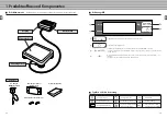
Page 4: ...racket x 2 Control Panel Symbols and their Meanings Level Gauge Display Box Battery Compartment Platform Accessories kg STABILIZED 0 0 Display Unit On Class II Equipment Display Unit Off Type B applie...

Page 5: ...ifference of more than 20 C leave at least two hours before using 8 Installation of the Equipment Prepare Power Source For accurate measurement place the unit on as flat a surface as possible and adju...

Page 6: ...hen will be displayed and t will appear next to 0 2 Step on the Platform and Start Measurement Please step on the Platform An arrow t will appear next to STABILIZED and the weight will be displayed 3...

Page 7: ...800 826 4828 Tel 847 640 9241 Fax 847 640 9261 http www tanita com Corporation Responsible in the EU Region The Barn Philpots Close Yiewsley West Drayton Middlesex UB7 7RY United Kingdom Tel 44 1895...

Page 8: ...elle 17 1 Produktaufbau und Komponenten 18 Produktkomponenten 18 Bedienungsfeld 19 Symbole und ihre Bedeutung 19 2 Vorbereitungen vor Gebrauch 20 H heneinstellung 20 Befestigung des Displays 20 Vorber...

Page 9: ...Feuchtigkeit oder starkem Staub aussetzen und nicht in der N he von Heizger ten oder in Bereichen die Vibrationen und St en ausgesetzt sind aufbewahren Wertebereich 230VAC 50Hz 65mA Spannungsbereich...

Page 10: ...nweise beachten Konformit t mit Medical Device Directive 93 42EWG Schaltet das Anzeigeger t ein und stellt die Anzeige auf Null Schaltet das Anzeigeger t ab Wenn die Plattform nicht belastet wird und...

Page 11: ...Stunden mit dem Gebrauch Vorbereiten der Stromquelle 21 Buchse Kontrolllampe Batteriefach Stecker Trockenb atterien Bundschrauben des Batteriefachs D 20 Befestigung des Displays Um ein genaues Messer...

Page 12: ...n chst in der folgenden Tabelle nach bevor Sie das Ger t in Reparatur geben M gliche Probleme 4 Fehlersuche D 1 Dr cken Sie die Taste Wie links angegeben blinkt nun auf der Anzeige auf gefolgt von Neb...

Page 13: ...47 640 9241 Fax 847 640 9261 http www tanita com Corporation Responsible in the EU Region The Barn Philpots Close Yiewsley West Drayton Middlesex UB7 7RY United Kingdom Tel 44 1895 438577 Fax 44 1895...

Page 14: ...entation 29 1 El ments constitutifs de la balance 30 El ments 30 Panneau de contr le 31 Liste et signification des symboles utilis s 31 2 Op rations effectuer avant la premi re utilisation 32 R glage...

Page 15: ...es modifications importantes de temp rature de l humidit de la poussi re des sources de chaleur et des vibrations et ou des chocs Valeur 230 V CA 50 Hz 65 mA Tension Fr quence Intensit F Applications...

Page 16: ...cessaire Attention Reportez vous aux notes ci contre Conformit avec la norme Medical Device Directive 93 42EEC Mettez le bo tier d affichage sous tension et remettez l affichage z ro Mettez le bo tier...

Page 17: ...ce de temp rature ambiante de plus de 20 C veuillez conserver la balance dans son nouvel emplacement pendant au moins deux heures avant de l utiliser Alimentation 33 T moin lumineux Connecteur jack Co...

Page 18: ...vous adresser un r parateur Probl mes possibles 4 D pannage F 1 Appuyez sur la touche Le message clignote l cran comme indiqu ci contre puis s affiche et la fl che t appara t en face de 0 2 Montez sur...

Page 19: ...www tanita com Corporation Responsible in the EU Region The Barn Philpots Close Yiewsley West Drayton Middlesex UB7 7RY United Kingdom Tel 44 1895 438577 Fax 44 1895 438511 http www tanita co uk Villa...

Page 20: ...prodotto e componenti 42 Componenti del prodotto 42 Pannello di controllo 43 Simboli e relativi significati 43 2 Preparazione per l uso 44 Regolazione del livello 44 Installazione dell apparecchio 44...

Page 21: ...di vibrazioni o colpi Range valore 230VAC 50Hz 65mA Range tensione Range frequenza Range corrente elettrica I Applicazioni Questo apparecchio stato calibrato come uno strumento di pesatura di precisio...

Page 22: ...ormit con Direttiva Dispositivi Medici 93 42 CEE Accendere l alimentazione dalla scatola del display e azzerare il display Spegnere l alimentazione per la scatola del display Quando non presente un ca...

Page 23: ...meno due ore prima di riutilizzarlo Preparazione della fonte di alimentazione 45 presa Spia Vano portabatteria spina Batterie Viti di fissaggio per il vano portabatterie I 44 Installazione dell appare...

Page 24: ...ere l effettuazione di riparazioni Problemi possibili 4 Risoluzione di problemi I 1 Premere il tasto lampeggia sul display come indicato a sinistra poi viene visualizzato e t appare accanto a 0 2 Sali...

Page 25: ...7 640 9241 Fax 847 640 9261 http www tanita com Corporation Responsible in the EU Region The Barn Philpots Close Yiewsley West Drayton Middlesex UB7 7RY United Kingdom Tel 44 1895 438577 Fax 44 1895 4...

Page 26: ...ntaje del producto y componentes 54 Componentes del producto 54 Panel de control 55 Los s mbolos y su significado 55 2 Preparaci n del equipo antes del uso 56 Ajuste del nivel 56 Instalaci n del equip...

Page 27: ...s Gama de frecuencias Margen de intensidad de la corriente el ctrica E Funciones Este equipo ha sido calibrado como instrumento de precisi n y puede ser usado para certificar pesos y o transacciones c...

Page 28: ...e referencia adjuntas En conformidad con la Directiva 93 42 CEErelativaalosproductossanitarios Encender el instrumento y poner display a cero Apagar el instrumento Cuando la plataforma no est cargada...

Page 29: ...20 C respecto a la anterior ubicaci n espere durante un periodo m nimo de dos horas antes de volver a utilizarlo Preparaci n de la fuente de alimentaci n 57 toma de corriente piloto Compartimento de l...

Page 30: ...ci n de problemas E 1 Pulse la tecla parpadear en la pantalla de visualizaci n como muestra el gr fico de la izquierda y a continuaci n se visualizar y aparecer t junto a 0 2 Suba a la plataforma y de...

Reviews: