3
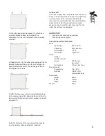
3. Using the two screws removed in 2, attach one
mounting bracket loosely to the side of the
Accessory, with the ‘ear’ towards the front, pointing
outwards.
4. Repeat 2 and 3 for the other side. Now push the lid
towards the back of the unit as far as it will go then
align the bracket ears with the front edge of the lid.
Now tighten the screws.
5. Offer the Accessory with its mounting brackets up
to the reverse side of the Mounting Panel, and fix it in
place using the two sets of screws, washers and nuts
removed in 1
Note that the holes at the rear ends of the brackets
may be used as cable tie-off points if desired.
OPERATION
The Power Supply has one indicator for each output.
These will both illuminate when the unit is operating
correctly. If one of the indicators should fail to
illuminate, this could mean that the output has been
shorted. Check that the connections are made
properly at each end of the jack lead, and that the
cable has not become damaged.
QUICK START
• Connect a jack lead to the accessory
• Connect the mains supply
TECHNICAL SPECIFICATIONS
Mains
Input range
85V to 230V
Frequency
50Hz to 60Hz
Consumption
<20W
Connection
3 pole IEC
Output
Voltage
12v DC nominal
Current
500mA max.
per output
Connections
3,5mm Jack (tip +)
Environmental
Temperature
0 to +45°C
Humidity
0 to 80% RH
(non-condensing)
Dimensions
Height
43mm
Width
115mm
Depth
115mm
Weight
500g


