background image

4

2.


With cabinet upside down, fix top cover 
frame into cabinet as demonstrated in 
(fig 3). Front edge of top cover to be 
3.0mm from front cabinet edge. Use the 
8g x 15mm pan head screws supplied 
and screw to cabinet to before fixing to 
the sides.

3.


Remove runners from drawer side as 
shown on page 6 using the release tabs 
in the side of the drawer, hold these 
forward while extending the runner out 
the back of the unit and then give a sharp 
pull to disengage from drawer.
Using the euro screw provided fix the 
runners to the cabinet sides in the 
position shown in (fig 4) utilising 
pre-drilled 5.0 fixing positions.

Fig. 4

Fig. 3

4.


Place cabinet back in upright position &
insert drawer chassis carefully. Slide back 
into cabinet and push firmly into place 
until you hear a click as the chassis locks 
into position on the runners.

Fig. 5

Summary of Contents for TBT30-212

Page 1: ... Models TBT30 210 TBT30 212 Installation Guide Your Handy Step By Step For further assistance in New Zealand www tanova co nz 0800 852 258 For further assistance in Australia www tanova com au 1300 123 700 ...

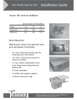
Page 2: ...nto cabinet 10 x M6 x 11mm Euro screws to fix runners to cabinet 6 x 6g x 15mm countersunk screws to fix drawer front connectors and gallery rails 2x Front connectors 2x Gallery rail expansion dowels 2x Drawer side cover caps Tanova TBT Series Installation Space Required for Installation Model W H D TBT30 210 267 365 510 TBT30 212 267 365 510 ...

Page 3: ...3 1 With your cabinet on its side fig1 mark fixing positions with a pencil see page 8 Using a 5 0mm drill pre drill the runner fixing holes Fig 2 Fig 1 ...

Page 4: ...e tabs in the side of the drawer hold these forward while extending the runner out the back of the unit and then give a sharp pull to disengage from drawer Using the euro screw provided fix the runners to the cabinet sides in the position shown in fig 4 utilising pre drilled 5 0 fixing positions Fig 4 Fig 3 4 Place cabinet back in upright position insert drawer chassis carefully Slide back into ca...

Page 5: ...6 Marking jig codes RMD 91230 Drawer front connector marking jig RMD 92130N Gallery rail marking jig If using marking jigs see fig 7 8 on right 6 Clip drawer front onto drawer and locate gallery rails fig 9 and fig 10 See fig 9 to release drawer front clips Model A B C TBT30 210 153 128 32 TBT30 212 153 128 32 A B C ...

Page 6: ...6 7 Adjust drawer front as indicated below Drawer Front Height and Tilt Adjustment Drawer Removal Drawer Insertion ...

Page 7: ...rawer front using two pan head screws and fix through two support points shown in fig 12 10 Insert waste bin buckets or laundry basket and you re ready to go 11 Bags can be fitted optional just raise handles and place bag liner in bin and around the rim now lower handles to hold bag open and firmly in place Fig 11 Fixing points for extra strength Fig 12 ...

Page 8: ...327 5 311 0 TBT30 210 TBT30 212 TANOVA WASTE RUNNER DRILLING SPECIFICATIONS 224 0 192 0 37 0 32 0 CABINET FRONT EDGE MEASURE FROM UNDERSIDE OF CABINET TOP TBT SERIES Fixing Positions ...

Reviews: