background image

3

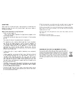
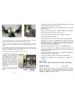
. Remove the terminal box cover (Fig. D) by sliding it half way out and noting which 

channel it is located in for refitting later. 
 

4

. Disconnect the wires to the neon light (Fig. E). The terminal box cover can now be 

fully removed as shown in Fig. F. 

Fig. E 

Fig. C 

Fig. D 

Fig. F 

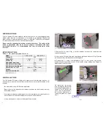
5

.  Lift  the  receiver  up  to  reveal  the 

brown  terminal  block  and  disconnect 
the  emitter  (lamp)  wires  noting  which 
ones  they  are  connected  to  as  shown 
in  Fig.  G.  Note.  The  middle  terminal  is 
not used on the emitter (lamp) side. 

RECEIVER 

Fig. G 

6

.  Loosen  the  sealing  gland  nut  (Fig.  H)  leaving  it  engaged  for  now  and  pull  the    

emitter  (lamp)  wires  out  of  the  terminal  block.  Check  the  emitter  (lamp)  wires  move 
freely through the sealing gland. If they are tight loosen the gland nut more or take out 
completely  noting  the  configuration  of  the  pressure  washer,  sleeve  and  2  ×  rubber 
seals inside. 

HORIZONTAL MOUNTING 

M O U N T I N G  


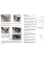
The  heater  must  be  mounted  in  a  horizontal 
(Fig. A)  manner only. 


When  mounting  the  heater,  do  not  position  the 
heater at an angle more than 75° and less than 
30°  from  the  mounting  surface  as  shown  in   
Fig. A. 


Always  allow  the  heater  to  cool  before            
attempting to reposition/move. Never attempt to 
move the heater while it is switched on! 


Observe  the  minimum  safe  distance  between 
the  heater  body  and  inflammable  surfaces  and 
objects when mounting.


Please  refer  to  Table  1  for  the  recommended 
positioning  of  the  heater.  Do  not  install  the 
heater in a corner!


Do  not  mount  the  heater  on  plastic  soffits  and 
fascia boards and ensure the mounting surface 
will suitably withstand the radiant heat from the 
heater body. 


Keep out of the reach of children.


1

.  Securely  fasten  the  heater  bracket  to  the 

mounting  surface  using  the  fixing  holes  in  the 
bracket. Please refer to Table 1 for recommended 
positioning of the heater. 
 

2

.  Fix  in  the  required  angular  position  by         

tightening the fixing bolt on the bracket at the rear 
of the heater (Fig. B). 
 

3

. Secure the supply cord to the mounting surface 

with  a  suitable  clip  so  the  cord  is  directed  away 
from the  heater  and  is  not  resting  on the  body  or 
obstructing the air-vents. 
 

Always  isolate  the  heater  from  the  mains   
supply when adjusting the angular position.


Fig. B 

Max. 75° 

Min. 30° 

2.

0m

 M

IN

H

EI

G

H

T

 F

RO

M

 F

L

O

O


GROUND LEVEL 

Fig. A 

Summary of Contents for Rio Grande RF GRAS-015RF-HW

Page 1: ...ve the right to make changes without notice 2017 TANSUN LIMITED Ref No 043262 Issue No A Rio Grande RF IMPORTANT SAVE THESE INSTRUCTIONS FOR FUTURE REFERENCE Reference Manual Rio Grande RF EUROPEAN MODEL HEATERS GRAS 015RF HW 230V 1 5kW GRAS 020RF HW 230V 2 0kW Spectrum House Unit 1 Ridgacre Road West Bromwich West Midlands B71 1BW England Tel 44 0 121 580 6200 Fax 44 0 121 580 6222 Email sales ta...

Page 2: ...aged from 3 years and less than 8 years shall not plug in regulate and clean the appliance or perform user maintenance CAUTION Some parts of the product can become very hot and cause burns Particular attention has been given where children and vulnerable people are present Remove the plug from the mains socket or disconnect pole switch during installation cleaning and or replacing the element and ...

Page 3: ...ord may overheat and cause a risk of fire Keep the mains supply cord away from the body of the heater which will get hot during use Arrange the mains supply cord so it cannot be tripped over or damaged Do not cover or obstruct the heater while it is in use Do not insert any object through any slot or opening in the heater Do not use if a guard is not present Do not install less than the minimum mo...

Page 4: ...ces If the supply cord becomes damaged it must be replaced by the manufacturer its service agent or a similar qualified person in order to avoid a hazard If in any doubt please contact a suitably qualified electrician Model GRAS 015RF GRAS 020RF Voltage V 230V Power kW 1 5kW 2 0kW Current A 6 5A 8 7A Min height from floor 2 0m Min distance from ceiling 0 3m Min distance from side wall 1 0m Dimensi...

Page 5: ... and less than 30 from the mounting surface as shown in Fig A Always allow the heater to cool before attempting to reposition move Never attempt to move the heater while it is switched on Observe the minimum safe distance between the heater body and inflammable surfaces and objects when mounting Please refer to Table 1 for the recommended positioning of the heater Do not install the heater in a co...

Page 6: ... lamps quartz glass causing premature failure YOUR REPLACEMENT EMITTER LAMP It is very important that your replacement emitter lamp is exactly the same as the one it was supplied with Failure to fit the exact same type could cause the heater to fail or even become dangerous especially when used in an outdoor environment Please contact your distributor to purchase your replacement emitter lamp and ...

Reviews: