background image

12

13

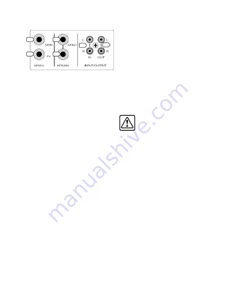
AUX SENDS and RETURNS

22. AUX 1 SEND MON OUTPUT 

To create a stage monitor mix, connect this 

1/4" TRS output to the input of your stage monitor 
amplifier (or powered monitors).

Each channel’s AUX SEND 1 MON (11) knob 

adjusts how much of the channel’s signal appears 
on the AUX 1 bus. The AUX 1 bus carries the sum of 
all those active channels whose AUX SEND 1 MON 
(11) knobs are set to more than minimum position.

The MASTER AUX SEND 1 (43) knob allows you 

to adjust the overall output level to your stage 
monitors.

You can use the internal 7-band graphic EQ (31) 

to equalize the monitor mix, by pressing in the MAIN 
MIX/AUX 1 (MON) (32) switch.

This output to your stage monitors is 

not

 affected 

by the channel FADERs (17) or MAIN MIX FADER (52). 
This is a good thing, as the monitors are not affected 
by level changes to your main mix. 

23. AUX 2 SEND FX OUTPUT

This 1/4" TRS output is intended to patch into an 

external effects processor, hence the name FX.

Each channel’s AUX SEND 2 FX (12) knob adjusts 

how much of that channel’s signal appears on 
the AUX 2 bus. The AUX 2 bus carries the sum of all 
active channels whose AUX 2 SEND FX (12) knobs 
are set to more than minimum.

The MASTER AUX SEND 2 (44) knob affects the final 

output level to your external processor. 

This output 

is

 affected by the channel FADERs 

(17), but not the MAIN MIX FADER (52).

Note:

 Before the AUX 2 signals reach the MASTER 

AUX SEND 2 FX (44) knob, a copy is tapped off to go 
to the internal Effects processor, and from there onto 
the main mix bus.

24. FX RETURN INPUTS

If you have an external effects processor, you can 

plug it into these inputs.

The incoming signals are added into the main mix, 

and a summed mono signal is added to the monitor 
mix. Adjustment is provided by the fascinating FX 
RETURN (45, 46) controls described in the Master 
section.

When connecting a mono device (just one cord), 

always use the left (mono) input and plug nothing 

into the right input. The signal will appear on both 
sides.


25. CD/TAPE INPUTS

This is where you connect the outputs of your 

intermission entertainment. Any line-level mono or 
stereo device can be used, such as: tape, DVD/CD 
player, television audio, etc.

Signals coming into these inputs are routed 

directly to the CD/TAPE TO MAIN MIX (49) control 
and through to the main mix. You will need to MUTE 
(14) all the other channels, if you just want to hear 
the CD or Tape.

The signals can also be routed to the control room 

and headphone outputs when the control room/
phones source select CD/TAPE (42) switch is pushed 
in.

When connecting a mono device (just one cord), 

you’ll need a “Y-splitter” RCA adapter. It turns a 
mono output cord into two cords, so both the right 
and left tape input jacks can be used. This adapter 
is widely available. See Appendix B for more 
information about RCA connectors.

Caution:

 There is a chance of feedback 

if you have the tape inputs and outputs 
connected to the same recorder, and the 
recorder is in record mode.

26. CD/TAPE OUTPUTS 

Use these RCA jacks to capture the entire 

performance to tape. The output signal is a direct 
copy of the main mix, as it appears at the MAIN 
MIX (58) outputs and the USB (62) output to your 
computer.

You could also use these outputs to connect 

to the unbalanced RCA inputs of a home stereo 
amplifier, if you had a mind to.

Do not use long runs of unbalanced cables, or 

there might be signal degradation and noise. Try 
using good quality cables as sold in Hi-Fi stores.

 Use the tape player’s record-level control to set 

up the correct levels for recording. Take care if you 
use the MAIN MIX FADER (52) to adjust the levels, as 
this will affect your MAIN MIX (58) outputs as well as 
these Tape outputs.

MASTER SECTION

So far, we have described the channels, and how 

the signals from all of your microphones, instruments, 
line-level sources and CDs or Tapes get onto the 
main mix buses, subgroups 1 to 4, and the Aux 
buses. Now we come to the Master section, which 
controls what happens next.

27. POWER LED

This light glows when the mixer is turned on. If it is 

off, the mixer will sulk and not work. Check that the 
rear panel power switch is on, that the power cord 
is plugged in, and any power strips or wall switches 
are on. Also check if all the lights are out in your 
neighborhood. You never know.

AUX

LINE

(

)

1

2

15

13

16

MUTE

GAIN

14

CD/ TAPE

15

16

MUTE

13

14

11

12

MUTE

11

12

9

(

)

(

)

(

)

GAIN

10

MUTE

9

10

PAN

PAN

PAN

LINE

LINE

LINE

GAIN

GAIN

PAN

EQ

MID

EQ

EQ

EQ

L

FX

R

1

2

AUX

1

2

AUX

1

2

AUX

1

2

AUX

HIGH

LOW

MID

HIGH

LOW

MID

HIGH

LOW

MID

HIGH

LOW

(

)

��

��

��

��

��

��
��

��

��

��

��

��

��

��
��

��

��

��

��

��

��

��
��

��

��

��

��

��

��

��
��

��

22

23

24

24

25

26

Summary of Contents for BLEND16

Page 1: ......

Page 2: ...ss To ensure against potentially dangerous exposure to high sound pressure levels it is recommended that all persons exposed to equipment capable of producing high sound pressure levels use hearing pr...

Page 3: ...st of the manual when nobody is looking Please keep your receipt in a safe sock drawer and write your product information here for future reference i e insurance claims tech support return authorizati...

Page 4: ...the sounds but if you prefer connect a set of headphones to the PHONES jack 2 Choose one of the microphones or instruments connected to the mono MIC INST or LINE inputs 3 Press that channel s SOLO sw...

Page 5: ...then turn the level controls back up When you shut down your equipment turn off any external amplifiers first When powering up turn on the amplifiers last Save the shipping box and packing material Th...

Page 6: ...ux1 control monitor FX Return to main mix control CD Tape to main mix control 8 segment stereo LED VU metering Solo LED Each subgroup can be assigned to Left and or Right of main mix 60 mm fader for e...

Page 7: ...7 SUB OUTS MAIN INSERT CONTROL RM OUT USB IN OUT MAIN OUT Hookup Diagrams Stereo PA system...

Page 8: ...8 SUB OUTS MAIN INSERT CONTROL RM OUT USB IN OUT MAIN OUT SUB OUTS MAIN INSERT CONTROL RM OUT USB IN OUT MAIN OUT Studio tracking and overdubbing Transferring records while yodelling and playing along...

Page 9: ...driven by virtually any line level signal Guitars and other instrument level sources should not be connected directly to inputs 3 8 You should use a preamp to provide a line level output first 3 INSE...

Page 10: ...ys in the right Careful use of PAN allows you to set up a nice stereo image in the left and right For the mono channels if PAN is in the center position the mono signal appears equally in both the lef...

Page 11: ...dd numbered channels and the right signals into even numbered channels 20 LINE PHONO switch channels 13 and 14 only In the up position channel 13 and 14 accept line level signals In the down position...

Page 12: ...c Signals coming into these inputs are routed directly to the CD TAPE TO MAIN MIX 49 control and through to the main mix You will need to MUTE 14 all the other channels if you just want to hear the CD...

Page 13: ...B either side of unity gain The frequency bands are 64 Hz 125 Hz 400 Hz 1 kHz 2 5 kHz 8 kHz and 16 kHz Adjust the EQ wisely and subtly Do not overdo the EQ gain as this might lead to overloading or cl...

Page 14: ...er will have a short reverb time and a larger number will have a longer reverb time 36 FX INPUT LEVEL and OL LED This knob allows you to adjust the signal level going into the internal effects process...

Page 15: ...ush MAIN MIX to hear the main mix Push CD TAPE to hear your CD or Tape player Push SUBS 1 2 to hear subgroup 1 and 2 outputs Push SUBS 3 4 to hear subgroup 3 and 4 outputs Note If any channel has its...

Page 16: ...ELECT 42 switches SUB 1 2 or SUB 3 4 are engaged The faders range from minimum at the bottom to unity gain at 75 up and to 10 at the top For an example of subgroups suppose you have a group of microph...

Page 17: ...then plug the power supply into a suitable and properly rated AC outlet 57 PHONO GROUND If you have a turntable connected use this screw terminal to connect the turntable s ground wire This will preve...

Page 18: ...he CD Tape input has a level control to adjust the amount of signal going onto the main mix The FX RETURN input has a similar control to adjust the level of internal and external effects going on to t...

Page 19: ...desirable echo of your recording Subgroups The channel audio signals can also be sent to the subgroups These let you group together similar or related sources For example your drum kit microphones can...

Page 20: ...nd assign 15 16 to the main mix Studio Software Monitoring Configuration 1 Follow steps 1 to 6 above to get your sounds into the computer using subgroups 1 2 Do not assign the subgroups to the main mi...

Page 21: ...gs and Jacks RCA type plugs also known as phono plugs and jacks are often used in home stereo and video equipment and in many other applications They are unbalanced and electrically equivalent to a 1...

Page 22: ...nput and Aux Return 18 dBu Maximum Voltage Gain Mic Input to Main Output 74 dB Tape Output 74 dB Aux Sends 74 dB Control Room Output 84 dB Phones Output 84 dB Inst Input to Main Output 49 dB Tape Outp...

Page 23: ...Hz or better is recommended for Tracktion At least 128 MB RAM 256 MB is recommended for heavy duty Tracktion work Super VGA 1024 x 768 or higher resolution video adapter and monitor CD ROM or DVD driv...

Page 24: ...V MIC HI Z CH1 2 3 BAND EQ 3 BAND EQ 3 BAND EQ LINE CH3 8 TO CH15 16 EQ IN CH15 16 CH13 14 CH9 12 TO CH13 14 EQ IN FROM USB INPUT D A CONVERTER USB SOURCE L R MONO CHANNELS 1 8 STEREO CHANNELS 9 12 ST...

Page 25: ...ne then you may be pushing your computer above it s limits Try increasing your latency settings as described above Large latency delay from input signal to output Change the latency buffer setting to...

Page 26: ...oblems Be sure you are running the latest drivers If after updating you still are having problems please call tech support Repair Service for TAPCO mixers is available at our corporate headquarters an...

Page 27: ...any location within the boundaries of the USA G LOUD Technologies warrants all repairs performed for 90 days or for the remainder of the warranty period This warranty does not extend to damage resulti...

Page 28: ......

Reviews: