


12
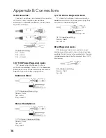
OUTPUT CONNECTIONS
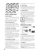
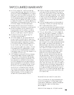
24. MAIN OUTPUTS
These 1/4" TRS jacks represent the end of the mixer
chain, where your fully mixed stereo signal enters the
real world.
Connect these outputs to the inputs of your
amplifi ers, powered speakers, or serial effects
processor (graphic equalizer, for example).
25. CTRL ROOM OUTPUTS
These 1/4" TRS jacks can be used to provide
another main mix output (with the CTRL ROOM (18)
switch set to MAINS), or to monitor the CD/Tape Inputs
(CTRL ROOM switch set to CD/TAPE).
Connect these outputs to the inputs of an amplifi er,
powered speakers, or recording device.
26. AUX SEND 1 MON OUTPUT
To create a stage monitor mix, connect this 1/4" TRS
output into your monitor amplifi er’s input, or powered
monitor’s input. This jack can also be used to feed the
inputs of an effects device.
Each channel strip has an AUX 1 MON (8) send
control knob that adjusts how much of that channel’s
signal appears at this output. The output from this jack
is the sum of all those active channels that have their
AUX 1 knobs set to more than the minimum position.
This output
is not
affected by the channel LEVEL
(11), or MAIN MIX (22) controls.
27. AUX SEND 2 FX OUTPUT
This 1/4" TRS output can be used to connect to the
input of an external effects device.
Each channel strip has an AUX 2 FX (9) control that
adjusts how much of that channel’s signal appears
at this output. The output from this jack is the mix of all
those active channels that have their AUX 2 knobs set
more than minimum.
This output
is
affected by the channel LEVEL (11),
but not the MAIN MIX (22) control.
Note:
Since this output is post-channel EQ and
LEVEL, it is not used as a traditional stage monitor cue.
It is intended to patch into an effects device’s input,
hence the name FX.
28. TAPE OUTPUTS
Use these jacks to capture the entire performance to
tape. The signal at these jacks is a sample of the main
mix, as it appears at the MAIN (24) output. The TAPE
OUTPUT level is affected by the MAIN MIX (22) control.
29. PHONES OUTPUT
The stereo signal at this output jack is the same as
the CTRL ROOM (25) outputs, but it is not affected by
the position of the CTRL ROOM (19) knob. You can
listen to the main mix, or the CD/TAPE, depending
upon the position of the CTRL ROOM (18) switch.
The PHONES (20) control allows you to set the levels
in your headphones as desired, without disturbing the
main mix or control room levels.
Note:
Be very careful because
the PHONES jack can drive any
standard headphones to very
loud levels. Please see page 2 for
information on hearing protection.
See Appendix B for information about 1/4" TRS
stereo connectors.
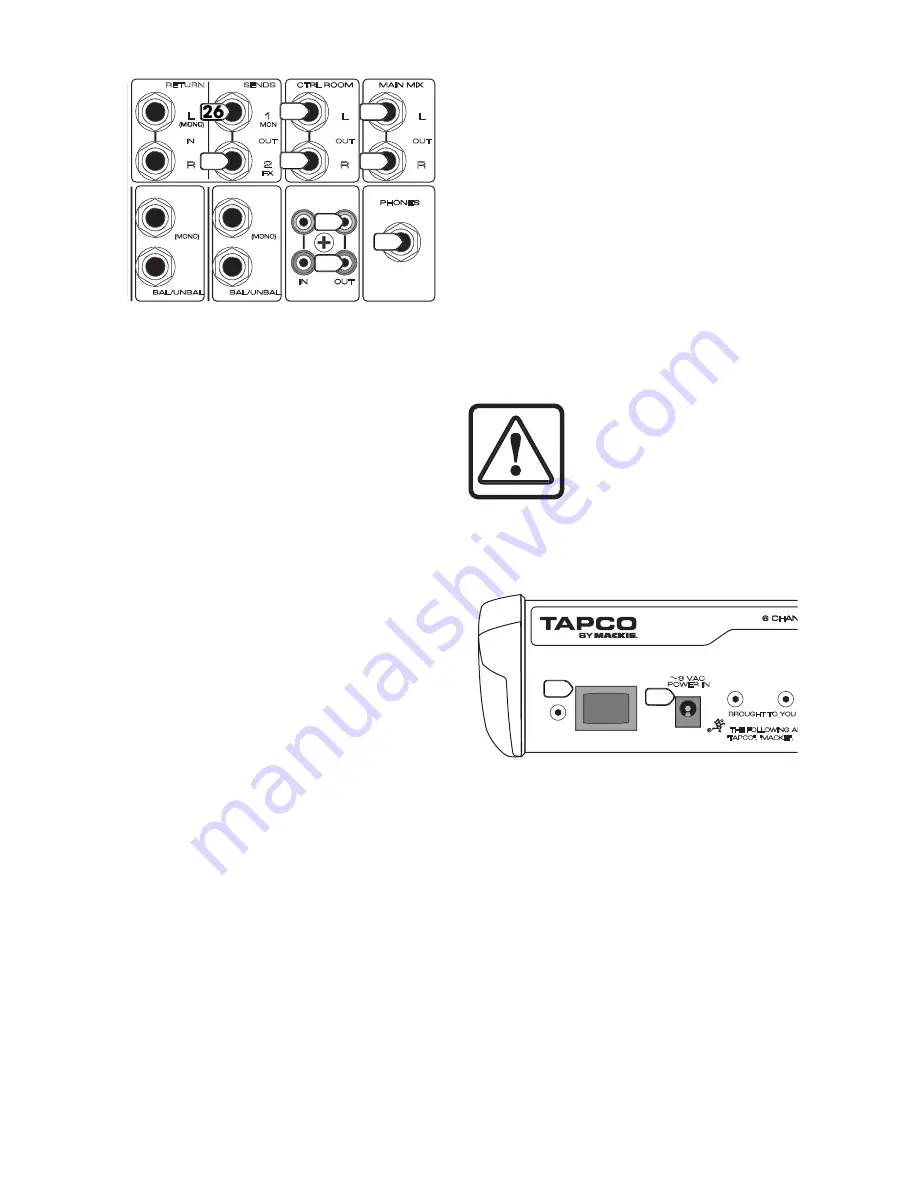
REAR PANEL FEATURES
30. POWER SWITCH
Push the side of the switch labeled “
ON
” to turn the
mixer on; you should see the
POWER
LED (16) glow
with happiness. To turn the mixer off, push the switch
the other way.
As a general rule, turn the mixer on fi rst, before any
amplifi ers or powered speakers. At the end of a show,
turn it off last. This will prevent any turn-on or turn-off
thumps from being heard in the speakers.
31. POWER IN
This connection is where you connect the supplied
external AC power supply to provide AC power to
the mixer. Connect the external power supply to the
Blend 6 fi rst, then plug the power supply into a suitable
and properly rated AC outlet.
WARNING:
Make sure you use the correct external
power supply capable of providing 9 VDC at 1.5 amps.
���
��� ������
�
�
�������
���
��� ������
�
�
�������
�
�
�
����
�
�
����
�
���
�����
���
�����
����
�����
��
���
������
�
�
�
�
�
���
�������
��
���
���
���
�������
��������
������
���
��
���
��� ����
�
�
�
�����
���
����
����
�����
�
���
��
���
��
�
�
�
��
���
�����
���
����
�
���
��
���
��
�
�
�
��
���
�
�
���
��
���
24
24
25
25
27
28
28
29
���������������
���������������
�������
��������
�������������������������������������������������������������
���������������
������������������������������������������������������������
������������������������������������������������������������������
POWER
ON
30
ON
ON
31


