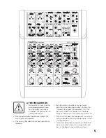
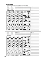
background image

4

Getting Started

The following steps will help you set up your mixer, and get the 
levels and adjustments just right.
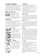
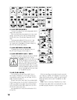
ZERO THE CONSOLE:

1.

Turn everything off, including the mixer’s POWER 
switch and PHANTOM POWER switch.

2.

Turn down the channel strip GAIN, AUX 1, AUX 2, 
and LEVEL controls.

3.

Center the channel strip EQ and PAN controls.

4.

Turn down the AUX RETURNS, CONTROL ROOM, 
and PHONES controls.

5.

Turn down the MAIN MIX control.
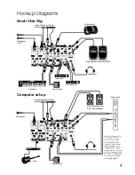
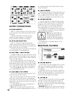
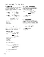
CONNECTIONS:

1.

Connect your speakers to your amplifi er’s outputs 
(unless, of course, you have powered speakers).

2.

Plug all the sound system components into suitable 
AC outlets, properly grounded and capable of 
delivering adequate current.

3.

Using TRS cables, make connections from your 
mixer’s MAIN OUT to your amplifi cation system’s 
line inputs. 

4.

Connect your microphones and instruments to the 
mixer: Connect microphones to the mono channel 
MIC jacks. (For condenser microphones, engage 
the PHANTOM POWER switch.) Connect high-
impedance line-level instruments (electric guitar, 
bass guitar) to the mono channel INST IN, or other 
line-level signal source to the stereo channel LINE 
IN jacks.

Note:

 Normally, you would plug in only one 

microphone or one instrument into each mono 
channel.

5.

Zero the console, as shown above.

6.

Turn all the power switches on, leaving the 
amplifi er’s switch for last.

7.

Turn up the MAIN MIX control to the 9 o’clock 
position, for now. We’ll crank it up later on.

8.

Now you are ready to set the levels.

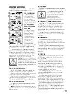
SET THE LEVELS (Channels 1 and 2):

1.

Choose one of the microphones or instruments 
you connected to the mono MIC or INST input. 
Make some noise. If it’s a microphone, sing at your 
normal singing volume. If it’s an instrument, play it 
at its normal output level.

2.

While making noise, turn up that channel’s GAIN 
until the adjacent LEVEL SET LED starts blinking.

3.

Raise that channel’s LEVEL to unity gain (

U

 label). 

You should be hearing your noise now.

4.

If necessary, apply channel EQ changes. (You may 
need to compensate for level changes afterward 
with the channel LEVEL control.)

5.

Repeat steps 1 through 4 for the other Mic/Line 
channel.

6.

Stop making noise. Everyone: start making music.

7.

Now turn up the MAIN MIX control to a 
comfortable listening level.

SET THE LEVELS (Channels 3/4 and 5/6):

1.

Make some noise with the mono or stereo 
instrument connected to the LINE IN jacks on 
Channels 3/4. Play it at its normal output level.

2.

Raise that channel’s LEVEL control until it 
is approximately equal in volume to the 
microphones or instruments connected to 
channels 1 and 2.

3.

If necessary, apply channel EQ changes. (You may 
need to compensate for level changes afterward 
with the channel LEVEL control.)

4.

Repeat steps 1 through 3 for Channels 5/6.

TWEAK THE MIX:

1.

If you are using an external processor connected 
between the AUX SEND 2 and the AUX RETURN jacks, 
use each channel’s AUX 2 FX control to send signal 
to the processor, and add the processor’s signal to 
the mix using the AUX RETURN TO MAIN MIX control.

2.

Now that you have a rough mix going, you 
may need to readjust the MAIN MIX control to 
a comfortable listening level. The LED VU meters 
should indicate by lighting most of the green LEDs 
when music is playing, and occasionally light the 
yellow LEDs.

3.

Depending on how much time you have, keep 
tweaking. Walk the room to see how it sounds 
away from your mixer. Keep tweaking. 

Summary of Contents for BLEND6

Page 1: ......

Page 2: ...from digital apparatus as set out in the radio interference regulations of the Canadian Department of Communications ATTENTION Le pr sent appareil num rique n met pas de bruits radio lectriques d pas...

Page 3: ...eep your receipt in a safe place and not a bad idea to write your product information here for future reference i e insurance claims tech support return authorization etc Contents Safety Instructions...

Page 4: ...ST input Make some noise If it s a microphone sing at your normal singing volume If it s an instrument play it at its normal output level 2 While making noise turn up that channel s GAIN until the adj...

Page 5: ...rs Before making connections to an external amplifier or reconfiguring an amp s routing turn the amp s level gain controls down turn the power off make the changes turn the power back on and then turn...

Page 6: ...tor Inter Planetary Space Drive control OK we made that last one up but we can pencil it in for next time Introduction Thank you for choosing a TAPCO Blend 6 mixer by Mackie The TAPCO family of mixers...

Page 7: ...UNBAL L R LINE IN 5 6 BAL UNBAL L R LINE IN 1 2 MONO MONO MIC INPUT MIC INPUT INST INPUT IN OUT L R PHONES L R L R R AUX SENDS IN OUT OUT AUX RETURN MAIN MIX CTRL ROOM FX MON CD TAPE MONO L LEVEL SET...

Page 8: ...ary 3 GAIN CONTROL If you haven t already please read SET THE LEVELS on page 4 The GAIN control adjusts the input sensitivity of the MIC and INST inputs This allows signals from the outside world to b...

Page 9: ...of the channel s stereo signals For instance channel 3 L and 4 R mix together to feed that channel s AUX send knobs 8 AUX 1 MON AUX 1 MON is designed to send a separate mono mix to your stage monitor...

Page 10: ...to howl as loud as the speakers ouch 15 CD TAPE INPUTS This is where you connect the outputs of your intermission entertainment Any line level mono or stereo device can be used such as tape DVD CD pl...

Page 11: ...a CD or Tape Deck connected to the CD TAPE inputs push down this switch to add the CD TAPE signal to the main mix This is useful if you want to play some entertainment while the band is taking a break...

Page 12: ...el EQ and LEVEL it is not used as a traditional stage monitor cue It is intended to patch into an effects device s input hence the name FX 28 TAPE OUTPUTS Use these jacks to capture the entire perform...

Page 13: ...packing box and must have the RA number on the box Once it s repaired we ll ship it back the same way in which it was received This paragraph does not necessarily apply to non warranty repair Warranty...

Page 14: ...Stereo Headphones 1 4 TRS Stereo Unbalanced Wiring 1 4 TRS Stereo Unbalanced Wiring Sleeve Shield Tip Left Ring Right 1 4 TS Phone Plugs and Jacks TS stands for Tip Sleeve the two connections availabl...

Page 15: ...els Mic Input 18 dBu Gain 3 dB Inst Input 18 dBu Gain 22 dB Stereo Line Input Tape Input and Aux Return 18 dBu Maximum Voltage Gain Mic Input to Main Output 74 dB Tape Output 74 dB Aux Sends 74 dB Con...

Page 16: ...hange these specifications at any time without notice During a recent Garden Fete put on by the Society for the Prevention of Misunderstandings SRSoF this mixer was accidentally awarded first prize in...

Page 17: ...O BLEND 6 BLOCK DIAGRAM SSE 01 04 L L R R PAN AUX 2 FX SUM THING SUM THING ELSE AUX RETURN TO MAIN MIX AUX RETURN TO AUX 1 MON AUX 1 MON L R L R LEFT MAIN BUS RIGHT MAIN BUS AUX 1 MON BUS AUX 2 FX BUS...

Page 18: ...18 Track Sheets Use these sheets to record some of your favorite settings 22dB 25dB 3 50 22dB 25dB 3 50 TAPCO Blend 6 NOTES 22dB 25dB 3 50 22dB 25dB 3 50 TAPCO Blend 6 NOTES...

Page 19: ...nologies to any location within the boundaries of the USA G LOUD Technologies warrants all repairs performed for 90 days or for the remainder of the warranty period This warranty does not extend to da...

Page 20: ......

Reviews: