background image

P R O 1 9   a n d   P R O 1 4   B r a k e s

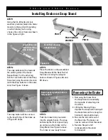
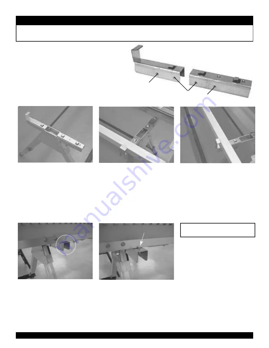
STEP 1

Using the 1/4-20 bolts and lock 

washers provided, fasten the brake 

mounts to the Leg Set. Depending 

on which brake you’re using, 

choose the correct holes as shown 

in the figure at right.

STEP 2

The snap buttons will be towards 

the working side of the brake. 

Repeat Step 1 for the other Leg 

Set. Be sure both ends of the Snap 

Stand are going the same direction 

(with the snap buttons on the same 

side). See Figure 2 above.

snap buttons are 

toward working 

side of brake

STEP 3

Place the brake on the assembled 

Snap Stand with the Back Rail of 

the brake clearing the adaptor 

hook as shown in Figures 3A and 

3B above.

Back Rail clearing 

adaptor hook

The snap button will be covered  

by the fixed hinge of the brake as  

in Figure 3C above.

STEP 4

Push the brake firmly rearward  

into the adaptor hooks. The snap 

buttons by the front clips will pop 

up and secure the brake on the 

Snap Stand. See Figure 4 above.

The brake is now ready for use.

Button pops up when brake is 

fully seated

1.  Removing the brake from  

the Snap Stand is essentially  

the opposite of attaching it to 

the stand.

2.  Lifting the Moving Hinge, 

depress the snap button and pull 

the brake forward far enough to 

hold each snap button down.

3.  Be sure the box rail is out of  

the Rear Clip. The brake can 

now be removed from the stand.

4.  Reverse Steps 2 and 1  

to disassemble the stand  

for transport.

Figure 2

Figure 4

Figure 3A

Figure 3B

Figure 3C

Removing the Brake:

PRO 14

PRO 19 & MAX-

I-MUM II

PRO 14

Installing Brake on Snap Stand

6

Summary of Contents for PRO14

Page 1: ...Tapco Products Company PRO Brake Operating Instructions...

Page 2: ...PRO Series Brakes PRO Cut Off Quickly safely and easily makes factory quality cuts in coil stock sheet metal and vinyl siding right on your Brake Snap Stand Heavy Duty Transportable Support sets up in...

Page 3: ...feed coil directly into the jaws of your PRO Brake Eliminates the need for a separate layout table Decreases damage from handling coil stock Clamping bar speeds up production helps decrease waste Att...

Page 4: ...m now on by simply removing the Faspins Insert Handle Assembly into hole in bot tom of Moving Hinge Align hole in hinge with Handle Plug and insert screw using T Handle Hex Key as shown Secure with 1...

Page 5: ...er there are a few basic necessities required to keep your Port O Bender like new 1 Clean the clamping surfaces each day before using Use only clean shop towels that are free of dirt oil and metal chi...

Page 6: ...ocations when legs are closed Snap Button locations when legs are open Attaching Optional Wheel Kit STEP 1 Insert the wheel assembly into the leg of the Snap Stand as shown in the gure above Tap the b...

Page 7: ...ail clearing adaptor hook The snap button will be covered by the xed hinge of the brake as in Figure 3C above STEP 4 Push the brake rmly rearward into the adaptor hooks The snap buttons by the front c...

Page 8: ...Down Down Up Up Up Up Up 1 All Purpose Sill Trim NOTE UP DOWN refers to the clad painted or FINISH SIDE of the material as it is placed into the Bender Down Down Down 2 3 1 2 3 1 Down 1 2 5 6 4 3 1 2...

Page 9: ...il 12070 10 6 HD Locking Anvil 12071 12 6 Locking Anvil 12071 12 6 Locking Anvil 12040 PRO 14 Parts Bag 12040 PRO 14 Parts Bag UNILINK ASSEMBLY 11944 Unilink 12098 Rubber Plug lug 12139 Unilink Washer...

Reviews: