background image

3

10/2015 EN

Practical Notes

Operation mode

With the potentiometer on the front plate the operartion mode can be 
adjustet. The adjustment must be required before energizied. Adjustment 
during energization is not allowed.
Only an automatic start at safety function two-hand control (3) is possible.

Start

Fkt. 1

Fkt. 2

1

MANUAL

MANUAL

2

MANUAL

AUTO

3

AUTO

HAND

4

AUTO

AUTO

5

MANUAL with common 

button

Line fault detection e.g. monitoring of ON-button

If the On-button pressed more than 3 s the adequate output contacts of the 
safety function can't be switch. The output contacts can be energized when 
the On-button pressed again (0.1 s < t

ON

 < 3 s).

A line fault is detected if the On-button more than 10 s is actuated. The 
output contacts of the adeauate safety function can only be energized with 
a reset or re-start with on an off switching of power supply.

ATTENTION - AUTOMATIC START!

According to IEC/EN 60 204-1 part 9.2.5.4.2 and 10.8.3 it is 

not allowed to restart automatically after emergency stop. 
Therefore the machine control has to disable the automatic  
start after emergency stop.

Reset and external failures:

The reset input is used to reset external failures (application failures or 
removable external failures as e.g. a line fault on reset button). If the reset 
signal is connected to the input for more than 3 sec the unit unit makes a 
reset. A new reset is only possible when the reset signal had been switched 
off temporarily.
If an external failure occurs because both input channels of a safety function 
did not switch on or off within the simultanious time, a reset is only possible 
if both channels are switched to off state after removing failure cause.
If an external failure occurs in only one safety function, only this function 
will be disconnected. The second safety function still continuous to work.

Function setting

The variants with selectable safety functions have 2 potentiometers Fkt.1 
and Fkt.2 to select the required function. The following functions are possible:

Fct. 1  / Fct. 2

Safety function

1

E-Stop

cross fault detection

2

Safety gate

3

Two-hand control

4

Safety mat / Safety edge

5

Exclusive or contacts

6

E-Stop

without 

cross fault detection

7

Safety gate

8

Light curtain

Indicators

green LED ON:  

on, when supply connected

red LED ERR:  

on, at internal error


flashes at external error

green LED K1/K2:  

on, when relay K1 and K2 energized
(safety function 1)
flashes at external errors of 
safety function 1

green LED K3/K4:  

on, when relay K3 and K4 energized
(safety function 2)
flashes at external errors of 
safety function 2

Operating Potentiometer

Poti "Start" 

Adjustment of operating mode 
Manual- or auto start for Fkt.1 and Fkt. 2.

Poti "Fkt.1" 

Adjustment of safety function 1

Poti "Fkt.2" 

Adjustment of safety function 2

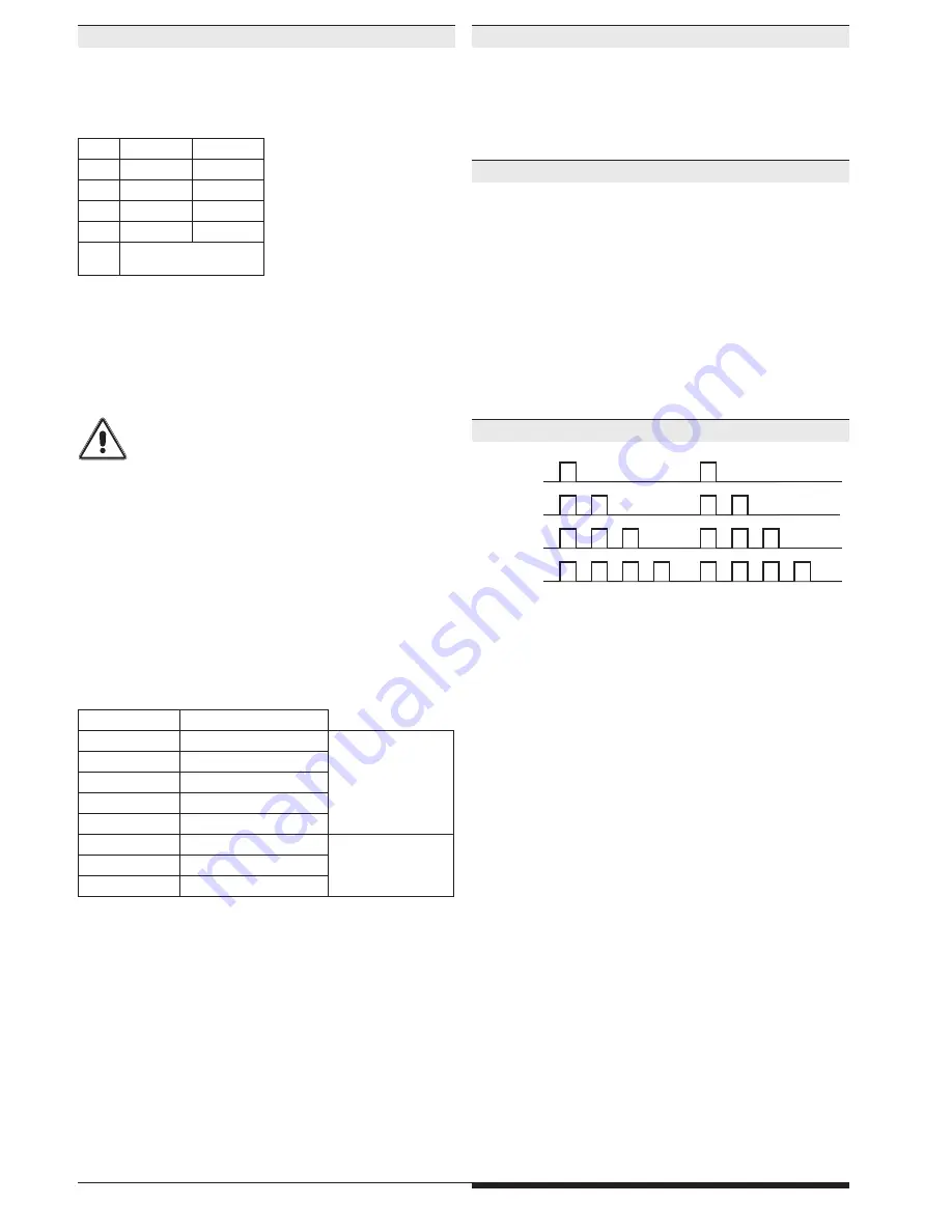
Fault Indication by Flashing Code

simultaneity
error

Potentiometer or
adjustment failure

line fault across
start button

Cross fault or

wiring fault

M10697_a

Summary of Contents for PRSU/M2SI

Page 1: ... is used for the safety related release and interruption of a safety circuit It can be used to protect people and machinery in applications with emergency stop pushbuttons safety gates self test type 4 photocells in accordance with IEC EN 61 496 1 two hand switches for metalworking presses and other working machines with dangerous closing movements Type III C according to EN 574 and for safety rel...

Page 2: ...his device presents no known residual risks Non observance may lead to personal injuries and damages to property The PRSU M2SI is used to enable and interrupt a safety circuit in a safe way It can be used to protect people and machines in applications with e stop buttons safety gates light curtains with selftesting Type 4 acc to IEC EN 61 496 1 2 hand controls for presses as well as other producti...

Page 3: ... A new reset is only possible when the reset signal had been switched off temporarily If an external failure occurs because both input channels of a safety function did not switch on or off within the simultanious time a reset is only possible if both channels are switched to off state after removing failure cause If an external failure occurs in only one safety function only this function will be...

Page 4: ...acts 5 Start up at UN 65 ms Release delay at UN and disconnecting the supply 40 ms Release delay at UN and disconnecting S12 S22 or S32 S42 60 ms Two hand control 3 Start up at UN 110 ms Release delay at UN and disconnecting the supply 40 ms Release delay at UN and disconnecting S12 S22 or S32 S42 60 ms simultaneity demand max 0 5 s Safety mat 4 Safety Edge Tapeswitch Start up at UN 85 ms Release ...

Page 5: ... 15 55 C Storage 25 85 C Altitude 2 000 m Clearance and creepage distance rated impuls voltage pollution degree 4 kV 2 IEC 60 664 1 EMC Electrostatic discharge ESD 8 kV air IEC EN 61 000 4 2 HF irradiation 10 V m IEC EN 61 000 4 3 Fast transients 2 kV IEC EN 61 000 4 4 Surge voltage between wires for power supply 1 kV IEC EN 61 000 4 5 between wire and ground 2 kV IEC EN 61 000 4 5 HF wire guided ...

Page 6: ...7 Auto Start Safety function 2 see page 7 Manual Start Operating mode 5 MANUAL with common button Safety function 1 see page 7 Manual start with common button Safety function 2 see page 7 Manual start with common button Application examples with safety function PRSU M2SI PRSU M2SI ...

Page 7: ...754 S22 S11 S12 S12 S1 M11124 S21 S22 S11 S12 M10753 Not Aus S21 Fct Safety mat Safety edge Tape switch 4 with cross fault detection SIL 3 PL e Cat 4 Fct Exclusive or contacts 5 with cross fault detection SIL 3 PL e Cat 4 Fct E Stop 6 without cross fault detection SIL 3 PL e Cat 4 1 S21 S22 S11 S12 Schiebeschutztür geschlossen M10752 OSSD1 OSSD2 S22 S21 S11 S12 Sender Empfänger DC 24V 0V M10751 Fc...

Page 8: ... A 0 6 x 3 5 0 5 Nm 5 LB IN M10248 A A 7 mm 1 x 0 2 2 5 mm2 1 x AWG 24 to 12 2 x 0 2 1 0 mm2 2 x AWG 24 to 18 M10249 A A 7 mm 1 x 0 25 2 5 mm2 1 x AWG 24 to 12 2 x 0 25 1 0 mm2 2 x AWG 24 to 18 M10250 A A 7 mm 1 x 0 2 2 5 mm2 1 x AWG 24 to 12 2 x 0 2 1 5 mm2 2 x AWG 24 to 16 Dimensions dimensions in mm A B PRSU M2SI 110 1 22 5 M4345_a M4345_a 35 115 3 0 0 7 122 6 0 0 7 B A 106 9 Mounting disassemb...

Page 9: ... variants are available on request The safety relevant data of the complete system has to be determined by the manufacturer of the system Approvals and Markings Demand to our device based on the evaluated neccessary safety level of the application Intervall for cyclic test of the safety function EN ISO 13849 1 PL e with Cat 3 or Cat 4 once per month PL d with Cat 3 once per year IEC EN 62061 IEC E...

Reviews: