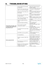
7.
MAINTENANCE
Tapflo LPX series
44
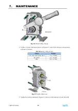
Tab. 7:
Cover spacer dimensions
Pump
I.D.
(mm)
O.D.
(mm)
Length
(mm)
25-1, 25-2, 40-1,
40-2, 50-1
14
25
18
50-2, 80-1
18
25
18
100-1
21
30
30
1.
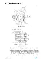
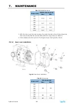
Install the rotor hub seal O-rings (Figure 54, item 53) into the groove of each shaft.
2.
Guide the body with seals installed over the studs and seat it firmly to the gear case.
Use care to prevent damage to the seals.
3.
Fix the body to the gear case using two spacers and acorn nuts (item 35) at opposite
corners of the body. See Table 7 for nominal dimensions required for spacers.
7.8.7.
Rotor positioning
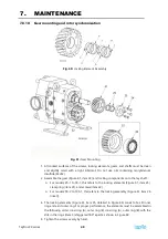
NOTE!
The screw holes in the rotors are designed to match the screw holes in the
shafts in only one orientation. To aid assembly, reference marks are provided on
each rotor and the end of the shaft.
Rotor clearances and synchronization require that each rotor must always be installed on
a specific shaft to maintain these clearances and prevent pump damage. The drive shaft
rotor, therefore, is marked with an ‘X’ in the lug screw counterbore. The marked rotor must
always be installed on the drive shaft.
7.8.8.
Rotor installation
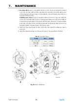
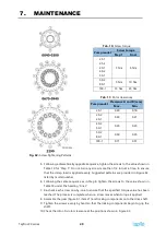
Fig. 55:
Rotor detail
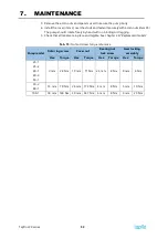
1.
The shaft bore of the rotors (Figure 55, item 3) must be clean and free of burrs and
debris (Figure 55, item B). The edge chamfer (item C) must be free of burrs to prevent
damage to the O-rings.
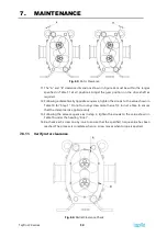
2.
The face of the shaft must be free of raised edges or burrs (see Figure 56, Detail G,
item D).
Summary of Contents for LPX Series
Page 59: ...9 PARTS LISTS Tapflo LPX series 59 9 3 Model 25 1 to 50 1 Pump Parts B exploded view ...
Page 61: ...9 PARTS LISTS Tapflo LPX series 61 9 5 Model 50 2 to 100 1 Pump Parts A exploded view ...
Page 63: ...9 PARTS LISTS Tapflo LPX series 63 9 7 Model 50 2 to 100 1 Pump Parts B exploded view ...
Page 69: ...Tapflo LPX series 69 ...

