7.
MAINTENANCE
Tapflo LPX series
46
7.8.9.
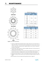
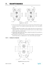
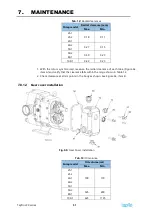
Setting rotor clearance
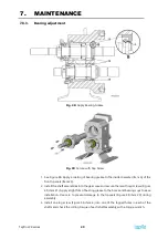
Fig. 57:
Rotor to Body Clearance
1.
Measure the clearance between the rotor and body as shown in Detail E, item A in
Figure 57. Record this number.
2.
Refer to Table 9. Subtract the “Clearance Target” for the appropriate model from the
clearance measurement. The resulting value is the total shim thickness that must be
installed behind the flange of the bearing case.
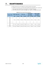
Tab. 9:
Back face and front face clearance
Pump model Clearance target
Acceptable range
Back face Front face
25-1
25-2
40-1
0.100
0.125
0.100
0.260
0.155
40-2
0.125
0.150
0.125
0.265
0.160
50-1
0.125
0.150
0.125
0.315
0.210
50-2
80-1
0.150
0.175
0.150
0.340
0.235
100-1
0.200
0.225
0.200
0.440
0.335
Summary of Contents for LPX Series
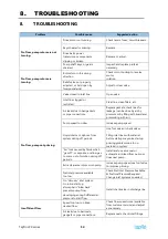
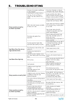
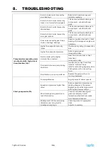
Page 59: ...9 PARTS LISTS Tapflo LPX series 59 9 3 Model 25 1 to 50 1 Pump Parts B exploded view ...
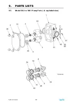
Page 61: ...9 PARTS LISTS Tapflo LPX series 61 9 5 Model 50 2 to 100 1 Pump Parts A exploded view ...
Page 63: ...9 PARTS LISTS Tapflo LPX series 63 9 7 Model 50 2 to 100 1 Pump Parts B exploded view ...
Page 69: ...Tapflo LPX series 69 ...


