7.
MAINTENANCE
Tapflo LPX series
48
7.8.10.
Gear mounting and rotor synchronization
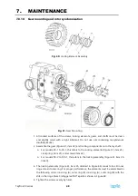
Fig. 60:
Locking Element Assembly
Fig. 61:
Gear Mounting
1.
All contact surfaces of the screws, locking elements, gears, and shafts must be clean
and slightly oiled with a light lubricant. Do not use oils containing molybdenum
disulfide (MoS2).
2.
Assemble the gear (Figure 61, item 22) and locking components onto the lay shaft.
For models 25-1 to 50-1, this refers to the locking elements (Figure 61, item 25),
clamp ring (item 23), and screws (item 24).
For models 50-2 to 100-1, this refers to the locking assembly (Figure 61, item 26
(inset)).
3.
The locking elements (Figure 61, item 25, detailed in Figure 60) consist of a slit inner
ring and a slit outer ring. For proper performance, the elements must be assembled in
the following order: inner ring (A), outer ring (B), inner ring (A), outer ring (B); with the
slits in the rings (item C) staggered 180° apart as shown in Figure 60.
4.
Tighten the screws evenly by hand.
Summary of Contents for LPX Series
Page 59: ...9 PARTS LISTS Tapflo LPX series 59 9 3 Model 25 1 to 50 1 Pump Parts B exploded view ...
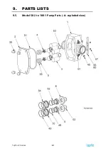
Page 61: ...9 PARTS LISTS Tapflo LPX series 61 9 5 Model 50 2 to 100 1 Pump Parts A exploded view ...
Page 63: ...9 PARTS LISTS Tapflo LPX series 63 9 7 Model 50 2 to 100 1 Pump Parts B exploded view ...
Page 69: ...Tapflo LPX series 69 ...


