7.
MAINTENANCE
Tapflo LPX series
50
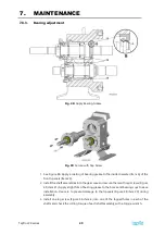
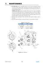
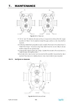
Fig. 63:
Rotor Clearance
11.
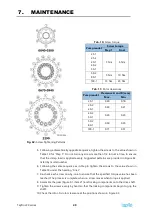
The “A” and “B” clearance dimensions shown in Figure 63 must be within the ranges
specified in Table 11 at all positions. Adjust the gear position on the drive shaft as
required.
12.
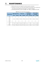
Following a diametrically opposite sequence, tighten the screws to the value shown in
Table 10 for “Step 1.” Do not turn any screw more than a 1/4 turn at a time to ensure
that the clamp load is applied evenly.
13.
Following the same sequence as in step 4, tighten the screws to the value shown in
Table 10 under the heading “Final.”
14.
Re-check each screw one-by-one to ensure that the specified torque value has been
reached. The process is complete when no screw moves when torque is applied.
7.8.11.
Verify rotor clearance
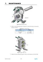
Fig. 64:
Radial Clearance Check
Summary of Contents for LPX Series
Page 59: ...9 PARTS LISTS Tapflo LPX series 59 9 3 Model 25 1 to 50 1 Pump Parts B exploded view ...
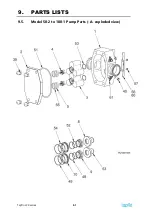
Page 61: ...9 PARTS LISTS Tapflo LPX series 61 9 5 Model 50 2 to 100 1 Pump Parts A exploded view ...
Page 63: ...9 PARTS LISTS Tapflo LPX series 63 9 7 Model 50 2 to 100 1 Pump Parts B exploded view ...
Page 69: ...Tapflo LPX series 69 ...


