7.
MAINTENANCE
Tapflo LPX series
52
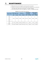
Tab. 14:
Grease volume
Pump model
Grease volume (ml)
Front
bearing
Rear
bearing
25-1
25-2
40-1
40-2
50-1
8.7
8.2
50-2
80-1
16.6
17.1
100-1
43.2
39.6
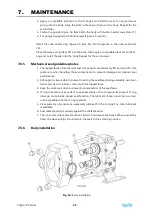
1.
Press the input shaft seal (Figure 65, item 29) into the bore of the gear cover (item 12).
2.
Place the gasket (item 50) over the dowel pins in the gear case.
3.
Lubricate the inside diameter of the seal with bearing grease and install the gear cover.
Use care to prevent damage to the lip seal when installing the cover.
4.
Install the cap screws (item 36) and washers (item 37) and tighten them evenly.
5.
Install the oil plugs (item 32) and level indicator plug (item 31) into the appropriate
locations for the pump mounting position.
6.
Fill with oil and install the breather plug (item 30). Table 13 provides oil capacity by
pump size and mounting position. The oil level should reach the center of the level
indicator.
7.
Grease the bearings. See Table 14 for the approximate volume of grease required for
the initial charge. For re-greasing a pump in service, see Table 3.
7.8.13.
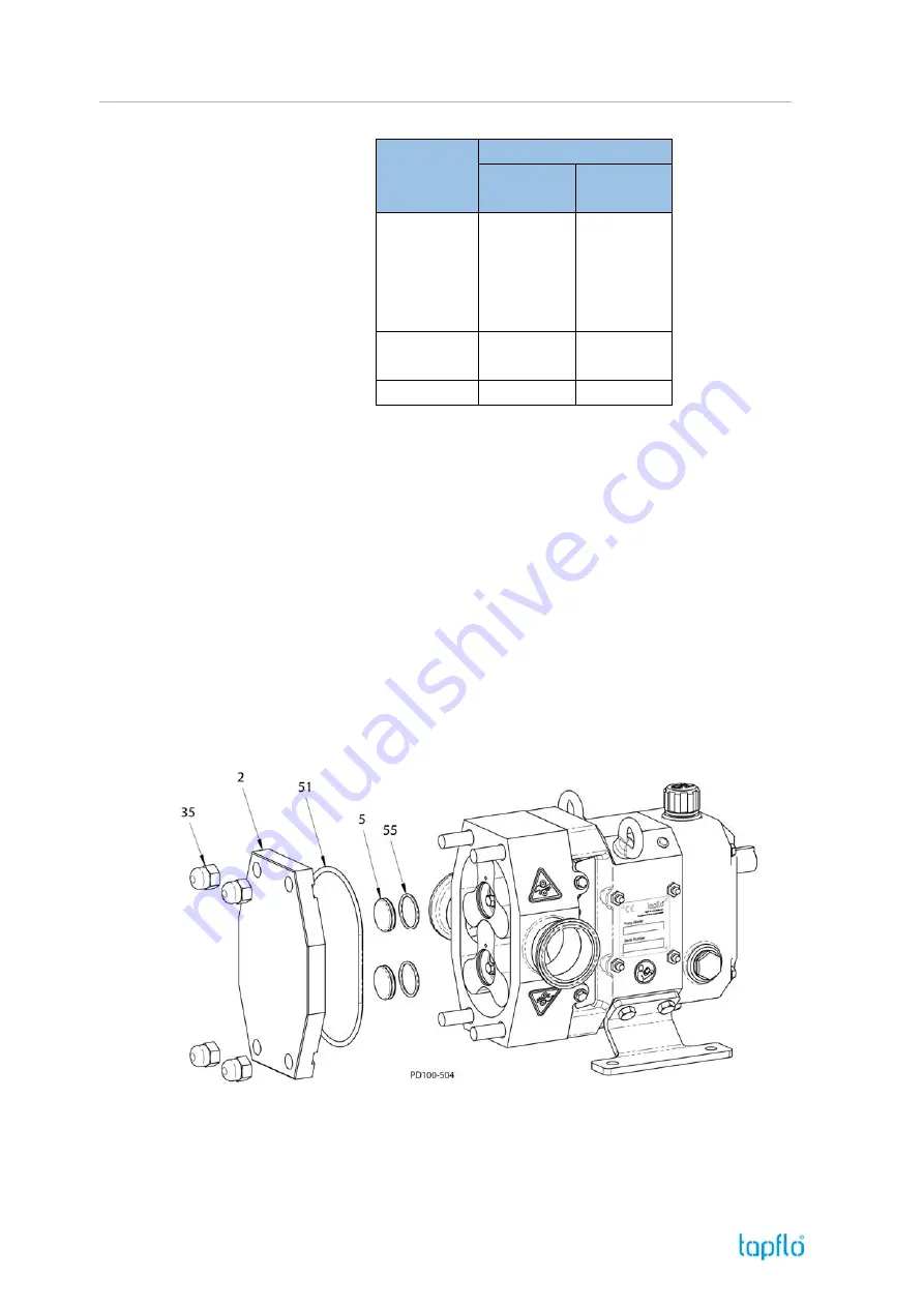
Cover installation
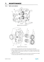
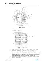
Fig. 66:
Cover Installation
1.
Install the screw cap O-ring (Figure 66, item 55) into the groove in the screw cap (item
5) and install it in the rotor bore. The O-ring snaps into the groove in the rotor bore.
2.
Install the cover O-ring (item 51) into the groove in the cover.
Summary of Contents for LPX Series
Page 59: ...9 PARTS LISTS Tapflo LPX series 59 9 3 Model 25 1 to 50 1 Pump Parts B exploded view ...
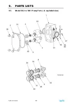
Page 61: ...9 PARTS LISTS Tapflo LPX series 61 9 5 Model 50 2 to 100 1 Pump Parts A exploded view ...
Page 63: ...9 PARTS LISTS Tapflo LPX series 63 9 7 Model 50 2 to 100 1 Pump Parts B exploded view ...
Page 69: ...Tapflo LPX series 69 ...

