background image


7106128 

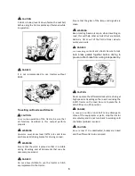
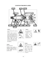
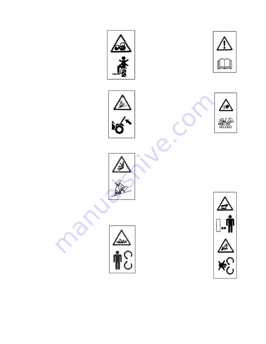
On  the  right  side of the safety 
frame. 

DANGER:  Hold  the  steering 
tightly  in  case  the  tractor  rolls 
over,  protection  bar  protects 
the  driver  unless  he  attempts 
to  stand  up  and  leave  the 
tractor. 

7106126 

On the left fender. 

CAUTION:  Do  not  carry  any 

other  passengers  on  the 

fender  or  any  other  place  or 

on an implement. 


7106127 

On  the  left  side  of  the  safety 
frame. 

CAUTION: Risk of rollover. Do 

not  remove  the  protection 

bar,  or  perform  drilling  or 

welding on it and do not hitch 

any implements to the bar. 


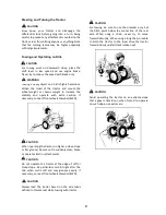
7106130 

On the power take off housing. 

DANGER:  Stay  away  from  the 

rotary  power  take  off  and  the 

connected  shaft.    Do  not 

attempt  to  disconnect  the 

cardan  shaft  from  the  power 

take off. Ensure tractor, cardan 

shaft 

and 

implement 

protections 

are 

properly 

installed and secured. 


7106261 

On the service sheet. 

CAUTION: 

Read 

the 

information  about  safety  and 

operation  of  the  tractor 

defined  in  maintenance  and 

instruction manuals. 


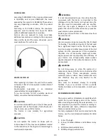
7106262 

On  the  right  side  of  the 
radiator separator sheet. 

CAUTION: Pressure hot water 

vapor.  Protect your face and 

hands  while  the  radiator  is 

hot,  radiator  contains  a 

certain  amount  of  pressure. 

Wait  until  the  engine  cools 

down before opening the cap 

and  turn  it  slowly  to  allow 

pressure to escape. 


7106263 

On  the  left  side  of  the 
radiator separator sheet. 

CAUTION:  There  are  hot 

surfaces,  stay  at  a  safe 

distance. 

CAUTION:  There  are  moving 

parts.  Keep  your  hands  away 

from  the  belt  and  moving 

parts  while  engine  operates. 

Ensure  the  protection  sheets 

are in place. 


14 

Summary of Contents for 850

Page 1: ......

Page 2: ......

Page 3: ...ill properly be carried out in order to keep the tractor in top mechanical condition at all times Should any information as to your tractor be required consult your local dealer or distributor stating the product model and its chassis and engine serial numbers of the Tractor concerned We are sure you will be happy with your Tractor NOTE The drawings used in this catalogue are for demonstration pur...

Page 4: ...ess Maltepe Mah Hastane Yolu Sok No 1 34010 Zeytinburnu İstanbul Telephone 90 212 5679550 Fax 90 212 6740679 90 212 6121239 e mail info taral com Web site www taral com ENGINE SERIAL NUMBER A Engine Identification Plate It is placed on the cylinder head B Engine Serial Number Barcode It is placed either on manifold or cylinder head C Engine Serial Number It is located at the right side of the cyli...

Page 5: ... may be operated with several implements however this manual may not give information about each possible implement to be used Consult your dealer or the factory about the conformity of such implements which are not described in this manual before using them TARAL may not be held liable for the damages or unexpected losses that may result from the incorrect installation handling of undescribed or ...

Page 6: ...axle 4 Replace traction oil 5 Retighten all bolts and nuts paying special attention to those for steering linkage and wheel 6 Check and adjust the fan belt tension 7 Check the wheels to see if their condition is good and tire pressure is correct 8 Retighten the cylinder head bolts and adjust valve clearances 9 Replace the air cleaner and clean its container 10 Replace the fuel filter and clean its...

Page 7: ......

Page 8: ...TERNAL VIEW AND NOMENCLATURE OF EACH PART 15 FRONT DASHBOARD CONTROLS 15 TRACTOR CONTROLS 15 SECTION 3 FUNCTIONS AND USAGE OF PARTS 17 INSTRUMENT PANEL 17 USAGE OF FRONT DASHBOARD CONTROLS 19 USAGE OF TRACTOR CONTROLS 20 TRANSMISSION 25 FRONT AXLE 25 HYDRAULIC LIFT 26 3 POINT LINKAGE SYSTEM 27 IMPLEMENT MOUNTING 28 IMPLEMENT REMOVAL 28 MIDDLE ARM CONNECTION 28 HITCH CONNECTIONS 29 POWER TAKE OFF H...

Page 9: ...RADIATOR 46 FUEL FILTER 47 ENGINE OIL FILTER 48 ENGINE OIL LEVEL 48 TRANSMISSION OIL FILTER 48 TRANSMISSION OIL LEVEL 48 BRAKE FLUID 49 ENGINE OIL REPLACEMENT 50 TRANSMISSION OIL REPLACEMENT 50 REPLACING THE OIL OF FRONT AXLE 51 LUBRICATION TABLE 52 REFUELLING 53 ADJUSTMENT OF FAN BELT TENSION 53 ADJUSTMENT OF CLUTCH PEDAL 54 FOOT CLUTCH PEDAL 54 HAND CLUTCH 54 BRAKE ADJUSTMENT 55 FOOT BRAKE 55 HA...

Page 10: ...DLAMPS 67 TRAILER SOCKET 67 ILLUMUNATION LAMPS 67 FUSES 68 GLOW PLUG 68 RELAYS 69 STARTER MOTOR 70 ALTERNATOR 70 INSTRUMENT PANEL WIRING DIAGRAM 71 OPENING THE BONNET 72 WASHING THE TRACTOR 72 SECTION 6 STORING 73 STORAGE 73 REOPERATION AFTER STORAGE 73 SECTION 7 TECHNICAL SPECIFICATIONS 75 TECHNICAL SPECIFICATIONS 75 ENGINE SPECIFICATIONS 76 SPEEDS VIA TIRES 76 TURNING RADIUS 77 ENGINE LUBRICATIO...

Page 11: ...80 3 POINT LINKAGE SYSTEM 80 ELECTRIC 80 CAPACITIES 80 UNIT CONVERSION TABLE 81 SECTION 8 TROUBLESHOOTING 83 ENGINE HARD TO START 83 BAD EXHAUST COLOUR 84 ENGINE STOPS ABRUPTLY 84 IN CASE ENGINE IS STOPPED ABRUPTLY 84 TRACTOR WILL NOT START 85 TRACTOR WILL NOT START 85 TRACTOR WILL NOT MOVE WITH ENGINE RUNNING 85 3 POINT LINKAGE SYSTEM WILL NOT MOVE 85 BATTERY PROBLEMS 86 ...

Page 12: ......

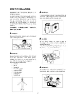
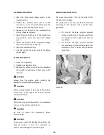
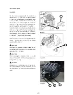
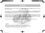
Page 13: ...ES AND EVEN DEATH ACCIDENTS ARE COSTLY ACCIDENTS CAN BE AVOIDED DANGER When the word DANGER appears next to this symbol it indicates the risk which may be resulted in serious injuries or even deaths if the subsequent precautions are not avoided CAUTION When the word CAUTION appears next to this symbol it indicates risks which may be resulted in serious injuries or even deaths if the subsequent pre...

Page 14: ... allow easy movement Avoid loose jackets mufflers ties scarves or loose shirt sleeves to prevent from being caught by moving parts Recommended protective items Helmet Mask Earphone Protective goggles Suitable clothes Reflective tapes Safety gloves Safety shoes It is recommended to have a fire extinguisher and a first aid kit in the vehicle Operator must know the place and utilization of these equi...

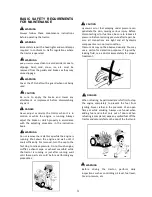
Page 15: ...er exhaust pipe or exhaust manifold while the tractor is running or just after running wait until these parts are cold before performing any procedures Hydraulic oil or fuel escaping under pressure can penetrate the skin causing serious injury Before disconnecting oil or fuel lines be sure to relieve all pressure Before restoring pressure after repair be sure all connections are tight and all hydr...

Page 16: ...lacked lime or bicarbonate of soda Wear suitable protective equipment such as goggles mask gloves etc when you are using the tractor for agricultural spraying purposes Zirai ilaçların teneffüs edilmesi veya direk temas edilmesi sağlığınız açısından bir risktir Inhalation of or direct contact with agricultural pesticides is risky for your health Daha detaylı bilgiler için ilacın kullanım kılavuzuna...

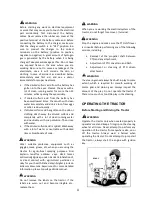
Page 17: ...tachment is completely touching the ground Do not leave the seat before tractor and the implement stops completely Slow down when operating the tractor on rough ground Never attempt to jump on or off a moving tractor When starting the tractor operating any attachment or engaging the PTO make sure that no one is in the way especially children When starting the engine in an enclosed area or building...

Page 18: ...are clean Keep rotating beacon lamp on when travelling on road this will help other vehicles that are distant behind a hill or out of the field of clear view to notice you easily For travelling on roads and streets be sure to lock both brake pedals together before driving to prevent either brake from acting independently Never operate the differential lock while driving at high speed or travelling...

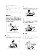
Page 19: ...ed Never remove or mount the implements when the tractor is operated or the parking brake is not applied Do not allow any person under the implement when the tractor is operated and the implement is in use Move the implement to the carrying position on road and tie and carry it without interrupting the driving and view of other travelling vehicles Avoid operating the tractor close to the areas whe...

Page 20: ... operating the tractor on higher a steep slope or flat ground be sure not to suddenly steer brake or operate clutch or attachments Do not operate the tractor at the edge of cliff or steep slope Be particularly careful right after the rain when soil is soft and may give way easily If necessary connect front wheels drawbar 4WD Always load the tractor based on the axle loads defined in this manual wh...

Page 21: ... km h or less in towing the tractor under 20 HP and at 15 km h or less in towing the tractor over 20 HP When towing or running on a steep downward slope be sure to apply the engine brake to keep safety speed Never run by inertia coasting with main shift lever placed NEUTRAL position or the clutch disengaged Using attachments To mount or operate attachments follow the instruction manual for the par...

Page 22: ... however do not attempt to traverse the slope When crossing the slope upwards or downwards the heavier part of the tractor must be always on the uphill side of the slope PREVENTING REAR ROLLOVER Do not pull loads using 3 point linkage arms or rear axle center line Use only the hitch hooks to pull loads Hitching the load at a high point may cause rear rollover and this may lead to serious injuries ...

Page 23: ... tire slip angle is designed to be 1 4 greater than rear tires Other values may cause tire wear and are not recommended Replace your tires with tires in the same sizes from the same brand We recommend using only low sulfur No 2 diesel for fuelling The clarity and purity of the fuel used has a significant impact on the life of the engine injectors pumps and other components of the fuel system and t...

Page 24: ...12 ...

Page 25: ...and brake lower the equipment place the shift and PTO shaft to the first position 7106123 Next to the battery CAUTION When working on the battery or electrical circuit remove the negative terminal of the battery from the electrical circuit 7106124 On the left side of the axle carrier CAUTION Always remove the terminal before performing any procedures on the electrical system 7106125 On the starter...

Page 26: ...nect the cardan shaft from the power take off Ensure tractor cardan shaft and implement protections are properly installed and secured 7106261 On the service sheet CAUTION Read the information about safety and operation of the tractor defined in maintenance and instruction manuals 7106262 On the right side of the radiator separator sheet CAUTION Pressure hot water vapor Protect your face and hands...

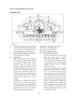
Page 27: ... TRACTOR CONTROLS 8 Operator s Seat 9 Shift Lever 10 Hand Throttle 11 Gas Pedal 12 Speed Shift Lever 13 Brake Pedal Lock 14 Right Brake Pedal 15 Left Brake Pedal 16 Clutch Pedal 17 Hand Operated Clutch Lever 18 Power Take Off Lever 19 Shuttle Shift Lever 20 Position Control Lever 21 Depth Control Lever 22 Parking Brake 23 Power Take Off Speed Lever 24 4 Wheel Drive Lever 25 External Power Outlet L...

Page 28: ...16 ...

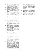
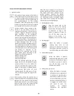
Page 29: ...hen 540 rpm is selected this value is shown with a turtle symbol and when 750 rpm is selected the value is indicated with a rabbit symbol Power take off speeds for engine speeds 540 Standard 2540 engine rpm 540 Economy 1875 engine rpm 750 Economy 2600 engine rpm S4 Water temperature gauge The water temperature pointer will move when the engine heats up Normal operating range of the engine is 75 C ...

Page 30: ...up when the PTO is applied if the PTO speed lever is at 750 L10 High beam warning light It lights in blue It lights up when the high beams are on or when the headlights are flashed L11 Low beam warning light It lights in green It lights up when the low beams are on L12 Fuel warning light It lights in yellow It lights up when the fuel level in the tank is under the limit L18 4 wheel drive warning l...

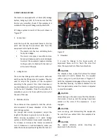
Page 31: ...ine If the engine is operated before the warning light goes off not recommended the light goes off and relay continues to glow the plugs for 20 seconds Start position When the ignition key is turned clockwise after the glow plug warning light goes off from ignition to this position starter motor starts to run and the engine starts As long as the key is placed at this position starter motor continu...

Page 32: ...ng to the weight of the operator by twisting the screw at the back side In order to adjust your seat forward or backwards pull up the lever 1 as seen in Figure 5 the seat will be secured when the lever is released OFF position Illumination is off First position Parking warning lights and dashboard background illumination is on Second position The low beam headlights are on To turn on the high beam...

Page 33: ...er 11 Gas Pedal Boosts engine rpm and enables the tractor to increase its speed It is operated by foot The speed increases as depressing continues and it turns to its original position after the pedal is released It can be used with hand throttle simultaneously if used when there is a fixed throttle setup the speed may increase even more When the pedal is released throttle setup starts to apply ag...

Page 34: ...the engine to the PTO and the PTO moves When the lever is in the lower position The clutch is activated there is no power transmission from the engine to the PTO and the PTO does not move In order to stop the PTO and disengage the clutch push down the A knob shown in Figure 8 until it locks when it locks you will hear a sound In order to move the PTO and engage the clutch pull the handle B shown i...

Page 35: ...When the lever shown in Figure 9 is pulled up it squeezes the brakes of the tractor thus ensuring stopping without slippage and parking To deactivate the parking brake press button 2 in Figure 9 and lower the lever 1 slowly downwards Normally there is one click play on the parking brake When activating and deactivating the parking brake also depress the service brakes to prevent the tractor from s...

Page 36: ...connecting terminals are supplied in the tool box together with the tractor Together with the tractor there is 1 hydraulic distribution valve with 2 dual effect independent circuits which can be converted to single effect It can be used to feed single effect and dual effect cylinders Control arms have 3 positions Above Hydraulic is given from outlet A Middle Circuit is closed Below Hydraulic is gi...

Page 37: ...cording to the work you will carry out and use it at the gear and rpm you determined FRONT AXLE Maximum oscillation angle of the front axle is 12 This is factory setting It is a setting determined by considering the axle the axle carrier the peripherals and dynamic movements do not alter this setting The permitted turning angle of the front axle is 40 in narrow axles and 45 in wide axles for the s...

Page 38: ...Pull the lever backwards to lift up the equipment Height of the equipment is directly proportional to the position of the lever The application travel is proportional to the position control lever 18 of the lift Depth Control Control is carried out by lever 20 shown in Figure 2 Immersion depth of the equipment is proportional to the resistance faced when driving The control valve changes the immer...

Page 39: ...ins can be adjusted to limit the side to side movement of lower drawbars of the three point linkage system For plough and similar equipment adjust the length of the chains to give a 5 to 6 cm free play While carrying equipment in 3 point linkage system restrict the lateral movements completely To increase or decrease the lateral movements turn it clockwise or counterclockwise when you make the des...

Page 40: ...le adjusting the drawbar and mounting the implement While carrying implement always keep the position control lever at the uppermost position and lock the hydraulic valve While mounting and dismounting the implement always use the position control lever Be sure to lower the implement before dismounting it Never work around the implement raised by the hydraulic system Secure the implement to preven...

Page 41: ...with the bolts 1 Figure 21 While attaching to the chassis the part 2 shown in Figure 19 is placed inside the bumper All the required parts have been supplied with the tractor For mounting you can use the toolkit supplied with the tractor While fixing the implement linkage always use the pin supplied with the tractor do not use another parts even if they are similar After combining the implement lo...

Page 42: ...hown in Figure 22 if further guidance is required All the required parts have been supplied with the tractor and they have been mounted on the tractor Do not try to remove or replace with other similar parts To obtain the offered performance replace the broken parts with the genuine parts at the authorized service stations To mount the parts it is necessary to tighten them with the special torque ...

Page 43: ...ed and after disengaging the clutch repeat the whole operation as described above If either of the left or right wheels has already begun slipping turn the throttle lever to the idle running or disengage the clutch then activate the differential lock You will hear an audible alarm while the differential lock engaged when the differential lock disengaged audible alarm will stop automatically NOTE B...

Page 44: ...power outputs and the description of the elements are provided below Descriptions of the parts in the circuit 1 Steering Cylinder 2 Pump 3 Hydraulic Filter 4 Differential Lock Cylinder 5 Hydraulic Control Valve 6 Hydraulic Distribution Valve 7 Orbitrol 8 PMV Valve 9 Hydraulic Lift Cylinders 10 External Outlet Quick Fit Couplings Figure 25 32 ...

Page 45: ...ELECTRICAL CIRCUIT The electric circuit diagram and the elements of the tractor are provided below Figure 26 33 ...

Page 46: ...ressures axle loads tracks and mounting types suitable to these tires in the following table The bold measurements shown in the Table 1 shows the factory defaults There may be variations in these values up to 20mm depending on the production RIM ASSEMBLY DETAILS Table 1 34 ...

Page 47: ...make sure that the rear and front wheel are tightened securely to specified torque and that the axle housing and gear case are secured each other to specified torque TIRE MOUNTING Make sure that rear tires are mounted so that the lugs on the tire form the staggered V s in series as viewed from the front of the tractor The tightening torque of the front and rear wheel nuts are 100 120Nm As they hav...

Page 48: ...ation could be performed 1 Valve 2 Water inlet 3 Water filling attachment 4 Air discharge Filling the Tires with Water 1 Raise the tire to be filled with water using a jack as valve positioned at the upper side 2 Remove the valve cap and release the tire pressure 3 Install the attachment 3 shown in Figure 29 to the valve 1 shown in Figure 29 and fill the water from the water opening 2 shown in Fig...

Page 49: ... Especially in cold areas to prevent freezing use antifreeze additives at require levels To avoid the corrosion could be found on the rims it is also recommended to add additives While water in the tires never operate the tractor above the 10 km h speed While attaching weights to the tires and filling the tires with water be careful not to exceed the maximum axle loads To inflate the tires never u...

Page 50: ...38 ...

Page 51: ...ngine 7 Immediately after starting release the ignition key The key will return to ON position automatically 8 Check the oil pressure and battery charge warning lamps to see they went off If not stop the engine immediately and inspect 9 Disengage the clutch and perform warm up run at about 1 500 rpm for about 5 minutes Use of the starter should be limited for about 10 seconds per trial If it is no...

Page 52: ... high speed interlocking the left and right brakes is particularly essential Be sure not to travel at high speed with left and right brakes being independent to each other not being interlocked 7 Do not attempt to stop tractor using brakes which may cause failure of transmission internals or prematured wear of brake linings 8 To avoid damaging brake or transmission system be sure to release the pa...

Page 53: ...sted if necessary STOPPING THE TRACTOR 1 By pulling throttle lever reduce engine speed 2 Depress clutch pedal all the way 3 Keep the brake depressed until the tractor comes to a complete stop 4 Place the PTO shift in the NEUTRAL position 5 Move main shift lever to NEUTRAL 6 Move the sloop lever to NEUTRAL 7 Remove foot off the clutch pedal slowly 8 Stop the engine by moving the ignition key to STO...

Page 54: ...42 ...

Page 55: ...p your tractor operating in the top condition is indispensable First service must be performed after the first 50 hours of running The service must be carried out in every 100 hours 150 and 250 hour services must be carried out in every 200 hours respectively Annual servicing must be performed for tractors that are slightly or never used See log book for more detailed about servicing Table 4 Perio...

Page 56: ...y to clean the radiator and replenish again as per the instruction described in this manual GENERAL RULES FOR MAINTENANCE The following section provides servicing instruction required for maintenance procedures When carrying out the maintenance services for tractor or its parts follow this instructions and perform the same sequence of procedures described Be sure to take safety precautions describ...

Page 57: ...ng gasket is checked it may be reused after washing with water and drying under shade If it is not clean enough you must replace it To clean the air cleaner push the clips 1 shown in Figure 30 towards A to unlock them pull the cover 2 towards 2 to remove Blow off with air the dust on the cover The filter has one cartridge inside and one outside Blow air from inside to outside to clean the external...

Page 58: ...is designed to function like an overflow jar The table below shows the amount of antifreeze solution that needs to be used depending on the season and weather conditions For the freezing temperature of antifreeze solution always refer to manufacturer s information first if it is not provided refer to the information provided in Table 5 Replace the radiator coolant fluid for every 1000 hours or at ...

Page 59: ...e 34 to drain the fuel in the tank Turn the filter housing 3 shown in Figure 34 with a filter wrench counterclockwise and remove it Clean the filter element in the filter housing if necessary if it is not possible to clean replace with a new one and tighten it To drain the water in the filter loosen the clogging plug 4 shown in Figure 34 and let the water drain away through the hose at the lower p...

Page 60: ...e 6 only as much as necessary to reach the proper level TRANSMISSION OIL FILTER To replace the transmission oil filter first drain all the transmission oil and turn the filter housing 1 shown in Figure 36 with a filter wrench counterclockwise to remove it Replace and tighten the filter element TRANSMISSION OIL LEVEL Place the tractor on a level ground to check the transmission oil level Check the ...

Page 61: ...it is inhaled or swallowed wash the contact area with plenty of water and immediately see your doctor The brake fluid can cause the paint of the tractor or other contacted areas flake away due to is chemical content Pay attention to avoid spilling out while using it Never try to replace brake fluid This requires post adjustment and removing the air from the system therefore it should only be perfo...

Page 62: ...oil into containers and deliver them to oil collection centers If you cannot find an oil collection center you can deliver the waste oil to authorized dealers TRANSMISSION OIL REPLACEMENT Move the 3P linkage arms to the lowest position before oil replacement First remove the cap 1 and plugs 1 shown in Figure 37 and Figure 41 respectively Then remove the plugs 1 and 2 seen in Figure 40 and wait unt...

Page 63: ...le 6 at the level specified without overflowing by placing a funnel on the plug holes 1 shown in Figure 42 After replenishing mount the plugs back and place the cover After oil replacement wait for 15 minutes to allow the oil to penetrate and check the oil level to make sure To check the front axle oil level remove the plugs 3 shown in Figure 42 Normally the oil level reaches just under this plug ...

Page 64: ... 140 Brake Fluid DOT 4 CASTROL Agri Classic 15W 40 GP 80W 90 Axle EPX 85W 140 Axle EPX 85W 140 Brake Fluid DOT 4 BP Vanellus Universal 15W 40 Hypo Gear 80W 90 Energear Hypo 85W 140 Energear Hypo 85W 140 Hydraulic Brake Fluid DOT 4 Amount lt 9 20 1 5 1 5 0 4 0 4 1 1 0 2 Specification API SL CF 4 API GL 4 API GL 5 API GL 5 DOT 4 Application Engine Transmission Front Axle Final Reducer Brakes No 1 2 ...

Page 65: ...jects at distance when refueling When refueling is completed place the cap back and securely fasten by twisting it counterclockwise until you hear a click sound After you hear the sound lock the tank cap by placing the ignition key to the slot on the cap and twist the key clockwise without moving the cap ADJUSTMENT OF FAN BELT TENSION Check fan belt tension periodically Proper deflection is 8 10mm...

Page 66: ...secure it HAND CLUTCH Hand clutch free play must be check on a daily basis The play of the foot clutch is appropriate if it is between 1 5 to 2 5 cm The free play must be adjusted if not appropriate To adjust hand clutch free play open the bonnet first and loosen or tighten the nut 1 seen in Figure 48 to reduce or increase the amount of free play respectively Normally it is not necessary to remove...

Page 67: ...er braking To adjust discs jack up the wheel to be adjusted only the wheel to be adjusted Twist and tighten the nut 1 seen in Figure 50 while at the same time turning the jacked up wheel by hand Continue to tighten the nut until the wheel is locked and is not able to be turned any more When the wheels are locked loosen the nut by a half turn Perform this procedure separately for each wheel Unbalan...

Page 68: ...cks on hand brakes AXIAL TRAVEL ADJUSTMENT OF FRONT AXLE When the axial travel amount of front axle increases it must be adjusted properly Jack up the front axle first to adjust axial travel Loosen the nut 1 seen in Figure 53 and adjust travel amount to 0 1 0 3mm by tightening the bolt 2 After the adjustment is completed secure the bolt with the lock nut 1 After the proper adjustment is obtained t...

Page 69: ...ommended and same size tires when replacing Different pairs of tires will cause earlier wear of the tires and overconsumption of the fuel due to the different slip angles Using larger size tires may cause trouble in terms of the resistance of the tractor and its interaction with the surrounding parts use recommended tires only To extend the life of your tires 1 Operate the tractor at the proper sh...

Page 70: ...st be performed fully If any problem occurs relating to the operation of the hydraulic system check the adjustments below When performing these adjustments mount a 150 kg weight to the links in order to see and evaluete the impact In order to adjust position control 1 Release the hydraulic valve lock 2 If the arms do not go up when the position control lever is pushed forward tighten the nut 1 see...

Page 71: ...r lose its function in time due to use If these parts are stuck during the operation or any other problem occurs the following locations should be greased For greasing use general purpose lithium Number 3 grease only WARNING Figure 57 Middle Arm Figure 58 Lifting Arm Figure 59 Clutch Shaft Figure 60 Brake Shaft 59 ...

Page 72: ...mounting of cylinder head requires expertise and special equipment the inspection must be performed only at authorized service centers Operator instructions provided in this section are only for information purpose When you need to open the cylinder head loosen the bolts in the same sequence with numbers from 18 to 1 as seen in Figure 63 When mounting the cylinder head tighten the bolts in the sam...

Page 73: ...e crankshaft from fan by hand or directly with key and check the clearance of marked valves with thickness gauge as seen in Figure 65 Adjust the valve clearances by loosening the lock nut B the adjusting screw A using a screwdriver and then applying a thickness gauge C When locking the adjusting screw by means of the lock nut B support the adjusting screw firmly using a screwdriver so that both ar...

Page 74: ... Definitions for the abbreviations on the flywheel are as follows 1 4 AZ Injection timing for 1st or 4th cylinder 1 4 UN Top dead center timing for 1st or 4th cylinder 2 3 AZ Injection timing for 2nd or 3rd cylinder 2 3 UN Top dead center timing for 2nd or 3rd cylinder There is a 360 one crankshaft cycle phase difference between the first cylinder and fourth cylinder There is a 360 one crankshaft ...

Page 75: ...s insufficient delay is required III under the level it means the advance is excessive it requires to be put forward To adjust injection timing it is required to add remove shims the parts 1 shown in Figure 71 under the pump To delay injection timing increase ignition timing e g from 10 to 12 reduce shims To put injection timing forward reduce ignition timing e g from 14 to 12 increase shims At th...

Page 76: ... the battery cable then use a wire brush for cleaning it 7 For the reinstallation of the battery make sure to set it on the battery support properly 8 For connecting the battery cables connect end of it first followed by earthing end 9 Check the electrolyte level after battery recharging if necessary add distilled water until it reaches the proper level 10 Check battery terminals for acidification...

Page 77: ...mmable gas it is very important that the environment is properly ventilated during charging Do not smoke and keep flaming objects at distance during charging After the engine is started remove the booster cables in the reversed procedure of above 1 First remove the end clip from the engine block of the troubled vehicle then remove another clip from the terminal of the normal vehicle 2 Then remove ...

Page 78: ...PROPER BATTERY SERVICE AND TIPS FOR SAFETY Table 7 66 ...

Page 79: ... of the tractor 3 Pull the tractor 5 meters backwards 4 Illumination cone of the head lamps must collide with the line drawn on the wall Maximum variation may be 130 mm 5 For each head lamp the distance between the refraction on the illumination cones and vertical line must be equal Maximum variation may be 50mm 6 If the adjustments above is not proper adjust by tightening loosening the screws 1 s...

Page 80: ...ity the body and the sheath come In contact with one another the glow signal lamp will be heated quickly and the wiring of the pre heated circuit will burn out See Figure 78 for locations of the fuses in the fuse box The circuits equipped with fuses are described below 1 Instrument Parking Lights 2 Main Illumination Parking Lamps 3 Rear Illumination Lamps 4 Left Hand Side Turn Signal 5 Right Hand ...

Page 81: ...Head Lamp High Beam Relay 5 Shut Off Solenoid Relay 6 Timer 7 Starter Relay 8 Glow Relay Relays are located under the tank except for the glow relay it is placed under the upper part of the dashboard housing To reach the relay bonnet tank and dashboard upper housing parts must be removed Contact your dealer in case of relay failures for repair or replacement Figure 79 Figure 80 1 5 2 3 6 7 4 8 69 ...

Page 82: ...e contact your dealer Pay attention to the following points about the alternator 1 If the polarity of alternator is reversed the diode will short circuit and burn and damaged 2 Never run the alternator engine with the battery disconnected When the battery is not connected voltage may increase excessively and it will be dangerous to contact with alternator leads 3 Do not ground the alternator termi...

Page 83: ...ight Negative J9 S4 Signal Inlet Ohm J10 Glow warning light Positive J11 S2 Signal Inlet Hz J12 Chassis Negative J13 PTO 540 Warning Light Negative J14 PTO 750 Warning Light Negative J15 High Beam Warning Light Positive J16 S1 Signal Inlet Ohm J17 Low beam warning light Positive J18 Fuel warning light Negative J20 4WD Warning Light Negative J21 Water Temperature Warning Light Negative J22 Left han...

Page 84: ...t is not fitted pull the bonnet up by releasing the latch as described above and close it again Be careful not to crash the bonnet over your hands or other persons hands or a body part WASHING THE TRACTOR When pressure washing the tractor safeguard the parts below and avoid washing the injection nozzles directly Alternator Starter Motor Battery and terminals Front axle rod arms and steering cylind...

Page 85: ...e end of the exhaust pipe 8 Clean the air cleaner and then cover it so as to seal the air intake system 9 Check the battery for proper electrolyte level and specific gravity at least once a month In order to increase the durability as well as prevent freezing the battery should be kept fully charged all the time REOPERATION AFTER STORAGE 1 Check to make sure that viscosity of the oil in the engine...

Page 86: ...74 ...

Page 87: ...SECTION 7 TECHNICAL SPECIFICATIONS Figure 83 Table 8 Technical Specs 75 ...

Page 88: ...NOTE The table above indicates forward speeds For reverse speeds multiply the speeds on the table by 0 988 Table 10 Speeds via Tires Table 9 Engine Specs 76 ...

Page 89: ...Figure 84 Table 11 Turning Radius 77 ...

Page 90: ...e Type Paper Filter Sensor Pressure 0 3 kgf cm2 absolute CLUTCH Clutch Type Dry Type Clutch Stage Double Clutch Size 9 Clutch Material Organic DIFFERENTIAL LOCK Control Type Electro Hydraulic Control Method Button Hydraulic Pressure 18 bar Deactivation Method Spring COOLING SYSTEM Radiator Capacity 5 liters Radiator Type Copper Radiator Cap Pressure 1 bar Circulation Pump Centrifuge Fan Diameter 4...

Page 91: ... Flow Rate 12cc rev 31 2 l d 2600 Pump 2 Pressure 180 bar BRAKES Brake Type Oil Bath Disc Number 4 2 2 Disc Material Organic Braking Mechanism Hydraulic Parking Brake Independent Mechanical STEERING Control Steering Cylinder Control Type Hydrostatic Maximum Steering Wheel Lock 1 5 FRONT AXLE Type 4WD Maximum Oscillation Angle 12 Maximum Turning Angle 45 40 Toe in Value 0 90 mm REAR HITCH Type Fixe...

Page 92: ...er Type and Number Single Effect 2 Safety Valve Pressure 180 bar External Power Output 3 8 Quick Fit Coupling 3P LINKAGE SYSTEM Class Category 2 CAT II Lift Equipment Linkage Point Vertical 1800 kgf Center Arm Pin Hole Dia 25 8 mm Lifting Arm Pin Hole Dia 29 mm ELECTRIC Battery 12V 75Ah Chassis Type Negative Chassis Alternator 45A Starter Motor 1 7 kW Glow Plug 30A CAPACITIES Fuel Tank 32 liters C...

Page 93: ...355 kW 1HP UK 0 7457 kW TORQUE 1 lbf in 0 1129 Nm 1 ozf in 0 00706 Nm PRESSURE 1 psi 6895 Pa 1 Torr 133 32 Pa 1 bar 100 kPa 1mmSS 9 8 Pa 1mmHgS 133 32 Pa 1m 39 37 inches 1m 99 97 cm 1m 1 00 m 1m 0 00062 statute miles 1m 0 00053 nautical miles 1cm3 0 0338 US ounces 1cm3 0 0352 Imperial ounces 1cm3 0 00026 US gallons 1cm3 0 00022 Imperial gallons 1cm3 0 0021 US pints 1cm3 0 0017 Imperial pints 1 cm3...

Page 94: ...82 ...

Page 95: ...ion nozzle Valve clearance out of range Adjust the valve clearance Valve leakage Tighten the valve Incorrect fuel injection timing Adjust the injection timing Engine oil thickens in cold weather slowing down the engine operation Replace the oil with an oil type suitable for the weather conditions Low compression pressure It is caused by bad valve adjustment or when the piston piston ring or liners...

Page 96: ... refuel if necessary Check the fuel system for air or leakage Deteriorated injector nozzle Replace with a new part if necessary Moving parts overheated Check the oil level with oil dipstick Check the lubrication system Check the oil filter Check the crank shaft end play IN CASE ENGINE IS STOPPED ABRUPTLY Possible Cause Remedy Speed increases decreases abruptly Consult your dealer for repair Low fu...

Page 97: ...er Engine oil might be thickened check the engine oil and replace it if necessary TRACTOR IS NOT MOVING WHILE ENGINE IS RUNNING Possible Cause Remedy Main shift lever or gearshift lever on Neutral position Move the shift levers to the position appropriate for the desired road speed Parking brake is applied Deactivate the parking brake Unadjusted foot clutch Get the foot clutch adjusted 3 POINT LIN...

Page 98: ...was not used for a long time Remove the battery when the tractor is not in use and recharge it regularly Replace the faulty battery Terminals highly corroded The connections are loose or the current of the alternator is too high Reduce the charging current of the alternators clean the terminals and tighten thoroughly and grease them Electrolyte level decreases suddenly Excessive charging causes ov...

Page 99: ...ONS THAT ARE NOT DESCRIBED IN THE INSTRUCTION MANUAL PLEASE CONSULT YOUR DEALER IN CASE OF FAILURE TO USE THE MACHINE PROPERLY AS INSTRUCTED IN THIS BOOK ALL RESPONSBILITY MUST BE UNDERTAKEN BY THE USER CAUTION 87 ...

Page 100: ...88 ...

Page 101: ......

Page 102: ...No 1 P K 34010 Zeytinburnu İSTANBUL Tel 90 212 5679550 Pbx Fax 90 212 6740679 1 90 212 6121239 e mail info taral com web site http www taral com TARAL reserves the right to change tractor design and specifications shown in this Instruction Manual at any time without prior notice ...

Reviews: