background image

3

Getting to Know Your Computer

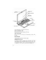
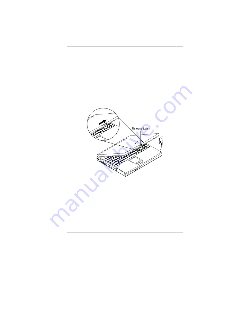
Opening the LCD Panel

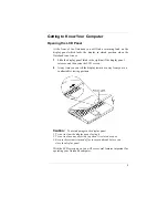
At the front of the Notebook you will find a retaining latch on the
display panel which locks the display in closed position when the
Notebook is not in use.

Slide the display panel latch to the right until the display panel
releases, and then raise the LCD screen.

At any time you can tilt the display toward or away from you to a
comfortable viewing position.

C

C

a

a

u

u

t

t

i

i

o

o

n

n

:

:


To avoid damage to the display panel:

1. Try not to slam the display upon closing it.
2. Try not to place any object on top when it is closed or open.
3. Be sure the system is turned off or in suspend mode before  you
    close the display panel.

With the LCD screen open, you will see several features important for
operating your Notebook computer.

Summary of Contents for Extender

Page 1: ...N No ot te eb bo oo ok k C Co om mp pu ut te er r U Us se er r s s M Ma an nu ua al l G797001...

Page 2: ......

Page 3: ...rm without prior written permission of the manufacturer Trademarks Phoenix is a trademark of Phoenix Technologies Ltd CardSoft is a trademark of SystemSoft Corporation AutoCAD and Autoshade are tradem...

Page 4: ...ii This page is intentionally blank...

Page 5: ...Power Source 13 Connecting the AC Adapter 13 Turning On Your Notebook Computer 15 About the ROM BIOS 15 About the Power On Self Test 15 Resetting the System 16 Adjusting the Brightness 16 Operating on...

Page 6: ...attery Power System 35 Removing the Battery Pack 35 Preparing the Battery Pack for Use 35 Automatic Battery Pack Charging Function 36 Battery Status 37 Battery Low Warning 39 Small Battery for the Rea...

Page 7: ...ling Software Drivers in Windows 98 77 VGA Display Drivers 77 Installing the Creative Sound Drivers 81 Installing Software Drivers in Windows NT 83 IDE Sound Driver 83 VGA Display Driver 84 Chapter 7...

Page 8: ...vi General 101 Mass Storage 102 Video System 102 Electrical 103 Mechanical 103 Operating Environment 103 Options 104 Software Specifications 104 Power Management Modes 104 Appendix B Index 105...

Page 9: ...does cause harmful interference to radio or television reception which can be determined by turning the equipment off and on the user is encouraged to try to correct the interference by one or more o...

Page 10: ...ting Devices This Class B digital apparatus meets all requirements of the Canadian Interference Causing Equipment Regulations Cet appareil numerique de la classe B repecte toutes les exigences du R gl...

Page 11: ...these openings must not be blocked or covered This product should never be placed near or over a radiator or heater Never push objects of any kind into this product through cabinet openings as they ma...

Page 12: ...ons are followed If the product has been dropped or the cabinet has been damaged If the product exhibits a distinct change in performance indicating a need for service Unless the manufacturer indicate...

Page 13: ...e Begleitmaterialien sorgsam auf Folgen Sie allen am Ger t angebrachten Warnungen und Hinweisen Vor dem Reinigen des Netzger ts Netzstecker ziehen Keine Fl ssigreiniger oder Spr hreiniger verwenden Zu...

Page 14: ...einen Nickel Kadmium Akku Im Interesse des Umweltschutzes bitte nicht mit dem Hausm ll entsorgen Eine Entsorgung kann je nach nationalen Vorschriften ber eine Kundendienststelle oder entsprechende Sam...

Page 15: ...tic Extended Graphics Array ECP Enhanced Capabilities Port EDO DRAM Extended Data Output DRAM EIDE Enhanced IDE Integrated Drive Electronics EPP Enhanced Parallel Port FDC Floppy disk controller FIR F...

Page 16: ...se Alternating Line A European color TV standard that broadcasts an analog signal at 625 lines of resolution 25 interlaced frames per second 50 half frames per second PCI Peripheral Component Intercon...

Page 17: ...details of your purchase Update this section when you add new options Date of Purchase Dealer s Name Phone Address E Mail Address WWW Site Type of LCD screen display Noted on the outside box q 12 1 C...

Page 18: ......

Page 19: ...ovide you with extra processing power for handling complex graphics and running large programs Two PCMCIA slots give you the ability to use standard PCMCIA cards such as a LAN adapter or memory cards...

Page 20: ...otebook computer An AC adapter An AC power cord A Standard Ni MH or Li Ion Battery Pack Software Drivers and Utility Diskettes This User s Manual A Carry Bag Do not throw the packaging materials away...

Page 21: ...s and then raise the LCD screen 2 At any time you can tilt the display toward or away from you to a comfortable viewing position C Ca au ut ti io on n To avoid damage to the display panel 1 Try not to...

Page 22: ...switch turns off the LCD backlight Stereo Speakers The internal speakers provide true stereo sound SVGA XGA LCD Screen Your Notebook computer is equipped with a replaceable color Liquid Crystal Displa...

Page 23: ...s on a standard mouse The PS 2 compatible mouse will work with the Notebook PC s TouchPad simultaneously System Status Indicator Panel The system status indicator panel keeps you informed of the compu...

Page 24: ...drive Indicates that the keyboard is in Num Lock mode Indicates when the keyboard is in Caps Lock mode In this mode the keyboard produces uppercase text when you press a key When you press the Caps Lo...

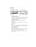
Page 25: ...ttery lock to the left when removing the battery module from the battery bay Battery Your Notebook comes equipped with a factory installed battery pack module After the battery runs down the module ca...

Page 26: ...which is also equipped with an IrDA compliant IR port This allows you to print documents without any inconvenient cable hookups Ventilation Opening Please don t block this opening during operation of...

Page 27: ...c to your Notebook PCMCIA Sockets Cover Open this cover to access the PCMCIA sockets The computer s PCMCIA sockets let you extend the capabilities of your computer by inserting PC cards The cards are...

Page 28: ...pening Please don t block these opening when the system is in operation Port Replicator Connector Connect the optional Port Replicator to the 20 pin Port Replicator connector The Port Replicator furth...

Page 29: ...s the Notebook s CPU and other internal components from becoming overheated Keep this fan unobstructed to allow proper ventilation to the Notebook s internal components There is an automatic thermal s...

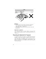
Page 30: ...e Internal K56flex Fax modem MDC module For more information refer to Installing Optional Devices in Chapter Four Preparing the Notebook for Transport To prepare the computer for transport you should...

Page 31: ...rect sunlight over a radiator or near a heat source for a long period of time High temperature can damage the circuitry If you are using the computer with the AC adapter do not allow anything to rest...

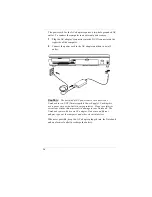
Page 32: ...ut ti io on n The best kind of AC power source to connect your Notebook to is a UPS Uninterruptible Power Supply Lacking this use a power strip with a built in surge protector Do not use inferior ext...

Page 33: ...lled it should start automatically To turn the Notebook off save your work and close all open applications click on Start then Shut Down and select Shut down the computer and click Yes or press the po...

Page 34: ...lly complete the POST but displays a blank screen emits a series of beeps or displays an error code consult your dealer Resetting the System After installing a software application package you may be...

Page 35: ...l batteries are not the same and therefore should not be treated as such Using the wrong battery could cause serious damage to your computer and yourself through toxic emissions Inserting and Removing...

Page 36: ...can be fully charged in about 2 5 hours when the computer is turned off or over four hour when the computer is on The Li Ion battery can be fully charged in about 4 hours when the computer is turned...

Page 37: ...help you work effectively without a lot of physical discomfort Purchase a chair with armrests and good back support Don t slouch when sitting keep your back straight Place the LCD panel or external m...

Page 38: ...20 This page is intentionally left blank...

Page 39: ...on an external CRT The LCD screen display results can be adjusted by changing the LCD panel angle and the display brightness Adjusting the LCD Screen Display The LCD screen display can be adjusted by...

Page 40: ...figurations are available LCD only Simultaneous display of the LCD screen and CRT monitor CRT only You can switch between these display configurations by pressing the key combination Fn F12 For inform...

Page 41: ...nd Alt Used by itself the Alternate Key has no effect in carrying out any commands but functions with the Ctrl and Del key Alt Ctrl Del to reboot or restart your operating system program Caps Lock The...

Page 42: ...he contrast level of the display For DSTN only Fn F6 Increases the contrast level of the display For DSTN only Fn F7 Decreases the brightness level Fn F8 Increases the brightness level Fn F9 This key...

Page 43: ...f 15 keys that make number intensive input more convenient Like the Num Lock key these keys are labeled in blue on the keycaps Numeric assignments are located at the upper right of each key When the n...

Page 44: ...off the space bar and on to the TouchPad 2 Gently move your thumb across the pressure sensitive TouchPad in the direction you want the cursor to move 3 The TouchPad offers a method of making selectio...

Page 45: ...r Microsoft s IntelliMouse When an external PS 2 device or Microsoft s IntelliMouse is connected to your system the touchpad will be automatically disabled Data Storage and Retrieval Data storage and...

Page 46: ...where diskettes are used or stored Particles from cigarette smoke are large enough to scratch the surface of the disk Store diskettes in a dry dust free environment C Ca au ut ti io on n Never turn o...

Page 47: ...DD module by sliding the latches in the opposite direction just as when you are releasing the HDD mentioned in Step 2 Close the HDD cover The CD ROM Features of the CD ROM Module The features of the C...

Page 48: ...he discs Loading a Disc To play a CD disc follow the instructions listed below 1 Push the CD ROM eject button on the CD drive door Gently pull the tray all the way out 2 Carefully lift the CD ROM by t...

Page 49: ...nal audio units An external microphone can be connected to the microphone jack External speakers or headphones can be connected to the Notebook s audio out jack External audio devices can be connected...

Page 50: ...IR Fast Infrared IrDA Infrared Data Association protocol Follow the guidelines listed below when using the Infrared Communication module to transmit or receive data Make sure the Infrared Communicatio...

Page 51: ...rned On or Off Follow these instructions to insert a PCMCIA card 1 Hold the PCMCIA card with the arrow side up and the connector side toward the socket 2 Align the card connectors with the appropriate...

Page 52: ...the switch setting and c re insert the card Power Saving Modes This section contains information on the Notebook s power system including the AC Adapter the battery system recharging the battery and t...

Page 53: ...k To remove the battery pack from its compartment please refer to Chapter Two Inserting and Removing the Battery Pack Preparing the Battery Pack for Use Before using the battery pack for the first tim...

Page 54: ...d mode Li Ion Battery Pack 4 hours with the system off or in Suspend mode Trickle Ni MH battery pack only When the system is on or off a trickle charge is supplied to the Ni MH battery pack to maintai...

Page 55: ...this program click on Start then Settings Click the Control Panel icon In the Control Panel double click the Power icon The screen will display the illustration shown below Click the box next to Show...

Page 56: ...een Power Scheme In setting your power options click on the Power Scheme tab to select the power scheme most appropriate for you in using your computer Home Office Desk Portable Laptop Always On Setti...

Page 57: ...source If the battery charge drops below a certain voltage level a beeping sound will prompt you to save your work and turn off the computer or connect the AC adapter The message is You should change...

Page 58: ...a PHDISK HDD partition has not been set the Notebook will suspend to DRAM You should connect AC power and resume to save your work Windows 95 OSR 2 has a Smart Battery function that allows you to chan...

Page 59: ...em Sleep mode Full Power Mode The computer operates in Full Power mode when power management is disabled When the computer is operating in Full Power Mode the Power LED remains on Standby Mode In addi...

Page 60: ...of inactivity the system enters Standby 3 After 10 additional minutes in the system Standby mode the system suspends to memory or disk After the system has suspended operation can be returned resumed...

Page 61: ...was initiated This does not mean however that all devices are powered up When the system resumes the following events occur DRAM refresh memory returns the system to the application that was running...

Page 62: ...detection schemes for determining true idle under DOS Windows and OS 2 Accounts for operating system inactivity and power demands Accounts for application inactivity and power demands Allows applicat...

Page 63: ...or IBM PS 2 compatible mouse The devices are hot pluggable You do not have to power down the Notebook to connect these devices 1 Plug the keyboard cable connector into the PS 2 keyboard socket on the...

Page 64: ...ernal monitor port Secure the screws on the connector 2 Plug the monitor s power cable into a wall outlet 3 Before you turn on the monitor turn on your computer and use the System Setup to designate t...

Page 65: ...s used to connect a peripheral device that can both input data to the computer and receive data from the computer The serial port is designated as COMA After you connect a peripheral device to the ser...

Page 66: ...l of record time to required storage ratio 3 D positional audio DirectX 5 0 Digitally controlled volume with muting Auxiliary line in and speaker line out for maximum flexibility Built in microphone a...

Page 67: ...ugh a single port USB Device You may optionally purchase a USB Universal Serial Bus for your Notebook computer USB devices such as mice keyboards and monitors are becoming more widespread throughout t...

Page 68: ...Optional Devices The K56flex Fax modem MDC module can be installed in the expansion card bay of the Notebook 1 Remove the Phillips screw from the expansion bay cover 1 and lift the cover free 2 Positi...

Page 69: ...the card so its connector mates with the mainboard connector 4 3 Replace the expansion bay cover and secure it with the screw you removed at Step 1 N No ot te e Before installing the Fax Modem card yo...

Page 70: ...52 This page is intentionally left blank...

Page 71: ...n configure such items as Hard drives and peripherals Bootup Drive Sequence Password protection Power Management Features The settings made in the BIOS Setup program intimately affect how the Notebook...

Page 72: ...FIR module Security Use this menu to set a password The password allows bootup and controls access to the BIOS setup menu Power Use this menu to configure and enable Power Management features Boot Us...

Page 73: ...key F5 Scrolls backward through the values for the highlighted field Plus key F6 Space Scrolls forward through the values for the highlighted field Home PgUp Moves the cursor to the field at the top...

Page 74: ...and down arrow keys to scroll through the entire help document Press the Home key to display the first page press End to go to the last page To exit the help window press the Enter or the Esc key Sav...

Page 75: ...format is month day year Use the Tab or Shift Tab keys to move between the month day and year fields Legacy Diskette A Specifies a drive type for diskette drive A Drive A is the factory included flopp...

Page 76: ...this field Auto default value None Select Auto to automatically configure an IDE type drive This option only works with standard IDE drives If your drive is an IDE type it will be automatically recogn...

Page 77: ...o User Heads This field configures the drive s number of read write heads Refer to your drive s documentation or look on the drive to determine the correct value to enter for this field If the system...

Page 78: ...ontroller This option supports PCI local bus only ISA bus is not supported Set the Type field to Auto to provide the optimum transfer mode Configuration options are Disabled default value Enabled Tran...

Page 79: ...ess the Enter key The Secondary Master submenu screen will appear When the Type field is set to Auto only the 32 Bit I O and Ultra DMA Mode fields are available When set to User the fields and options...

Page 80: ...ach field on this submenu is covered below Serial Port A This field allows you to configure the Notebook s serial COM1 port The following options are available Disabled Enabled Auto default value When...

Page 81: ...IRQ settings for COM1 COM2 and the LPT Port can cause conflicts with other system devices or installed peripherals Mode This field allows you to configure the Notebook s parallel port transmission mo...

Page 82: ...operations Second the host performs a series of read and or write byte operations to the selected register There are four operations supported by EPP Address Write Data Write Address Read and Data Re...

Page 83: ...akes no difference If you forget your password your system will have to be sent to the dealer to have it removed at your expense User Password Is This field will show Set when you have set a User Pass...

Page 84: ...now cleared Set User Password This field allows you to set the User password To set the User password follow the same instructions for setting the Supervisor password The User password allows restrict...

Page 85: ...visor only the Supervisor password will allow access to the FDD The options for this field are User Supervisor default value Virus Check Reminder When enabled displays a reminder to check the system f...

Page 86: ...Power Savings This option must be enabled to use any of the automatic power saving features The options for this field are Disabled default value Customized Maximum Power Savings Maximum Performance...

Page 87: ...lows you to specify how much time of inactivity must elapse before the system automatically transits to Standby mode In Standby mode all devices are powered off and the system enters a low power CPU s...

Page 88: ...Suspend Mode This field determines whether the Notebook will save its CPU status and Suspend to its lowest power consumption mode or Suspend to disk and power off Available options for this field are...

Page 89: ...esume normal operation at 1 00 PM by setting this field with a value of 13 00 hours The Boot Menu The Boot menu allows the user to specify the order in which the Notebook is to check for a device to b...

Page 90: ...t the boot device Then press the plus key to move the device up the list or the minus key to move the device down the list After you have made your changes to the Boot Device Priority menu press Esc t...

Page 91: ...xit menu to ensure the values you selected are saved to Non Volatile RAM Setup Confirmation Save configuration changes and exit now Yes No Select Yes to save changes and exit the BIOS setup program or...

Page 92: ...e changes to the fields other than system date system time and password the system will ask for confirmation when choosing Exit Discarding Changes Warning Configuration has not been saved Save before...

Page 93: ...tions without exiting the Setup program You can then return to other menus and make changes Setup Confirmation Save configuration changes now Yes No Select Yes to save any changes to Non Volatile RAM...

Page 94: ...76 This page is intentionally left blank...

Page 95: ...98 VGA Display Drivers This section describes the operation and installation of VGA display software drivers supplied on the Driver Utility CD ROM that is shipped with your computer 1 Insert the CD RO...

Page 96: ...b and click on the Advanced tab to enter the RAGE MOBILITY AGP English Properties window You will notice three new entries have been made in the Display Properties window ATI Displays and ATI Color AT...

Page 97: ...ATI Display tab 4 Select the Monitor or TV tab by clicking on the button on the upper left corner to enable and connect the video display to the monitor or TV screen 5 Click on the button at the lower...

Page 98: ...area in the Display Area Use your touch pad or mouse cursor to point at any area of the screen to move the window screen to a larger view To achieve the Dual View function follow the procedures below...

Page 99: ...Sound Drivers To install the sound driver you must first remove the currently installed driver and then install the Creative Sound driver 1 Click Start then click Settings 2 Double click the System ic...

Page 100: ...ve letter 4 The CREATIVE Software Installation window is shown on your screen 5 Follow the Wizard s on screen instructions to complete the installation From the directory of C Creative EV1938 you will...

Page 101: ...g then click on the Control Panel Double click on the Multimedia icon and select the Devices tab 3 Click on the Add button and select the Unlisted or updated driver and click OK 4 From the Install Dri...

Page 102: ...Driver 1 Insert the ATI Installation CD ROM into your CD ROM drive 2 Click Start and Select Run 3 Type the following D VGA NTVGA NT_b51 Setup If D is not your CD ROM drive substitute D with the correc...

Page 103: ...ional parameters The PHDISK options can be called by using only the first letter of each option and parameter For instance either PHDISK REFORMAT or PHDISK R will invoke the reformat option Option Par...

Page 104: ...hard disk drive large enough to store all data present in the segment The CREATE option formats the Save to Disk partition or file marking bad spots on the hard disk drive as they are found Automatic...

Page 105: ...ed amount is allocated If the user specified amount is less than the calculated amount then no space is allocated and an error message is displayed If you wish to allocate a specific amount of disk sp...

Page 106: ...k file space adds the amount of additional memory required as calculated by PHDISK PHDISK CREATE PARTITION PHDISK C P Creates a Save to Disk partition using the amount of memory required as calculated...

Page 107: ...o actually remove the Save to Disk space use the DOS FORMAT command DELETE Option Syntax Command Description PHDISK DELETE FILE PHDISK D F Deletes the contents of the Save to Disk file PHDISK DELETE P...

Page 108: ...ages not all of which are listed here The following list emphasizes the error messages including a possible course of action should one of them appear PHDISK Sign on Message Help Screen The HELP scree...

Page 109: ...Run a hard disk utility program to determine the source of the error then run PHDISK again Not Enough Disk Space The following text is displayed when the amount of unused disk space available is less...

Page 110: ...ute PHDISK CREATE FILE to create a Save to Disk file First Two Sectors Bad The following text is displayed when the Save to Disk partition cannot be used Execute PHDISK PARTITION DELETE and PHDISK PAR...

Page 111: ...System Memory The following text is displayed when not enough system memory is available to run PHDISK Add more system memory then try the PHDISK command again File Already Exists The following text...

Page 112: ...94 This page is intentionally blank...

Page 113: ...zed approach to solving the problem The problems that you will encounter can be divided into two basic categories hardware problems and software problems Hardware problems can be further divided into...

Page 114: ...for checking the power You may also need to check the fuses and breakers in your electric box If the outlet is controlled by a wall switch make sure that the switch is on If the outlet is controlled...

Page 115: ...rom operating at all or could cause incorrect and apparent results An example of a critical error is microprocessor malfunction Messages that furnish important information on the power on and boot pro...

Page 116: ...ask bar or in the control panel If the date and time become incorrect after a short time your CMOS battery may be depleted Contact your dealer to change the battery P Pr ro ob bl le em m The message I...

Page 117: ...disk has been formatted Consult your operating system manual for information on formatting floppy diskettes P Pr ro ob bl le em m The diskette is write protected Eject the diskette remove the write pr...

Page 118: ...be taken to the shop Before you call your dealer however prepare the following information How is your computer configured Your dealer needs to know what peripheral devices you are using What message...

Page 119: ...oard Two 144 pin SODIMM Slots 3 3V TSOP DRAM Supports 66 440ZXm 100MHz 440ZX Synchronous DRAM Core Logic Chips Intel 440ZXm 440BX L2 Cache Memory Supports 128KB L2 PBSRAM cache PCMCIA Sockets Two PCMC...

Page 120: ...xternal AC adapter TV out port S connector Two PCMCIA type II or one PCMCIA type III slots 20 pin port replicator connector One Universal Serial Bus USB port One line in jack One headphone line out SP...

Page 121: ...charger Charge modes System on 5 hours charge time Ni MH battery 4 5 hours charge time Li Ion battery System off or in Suspend mode 2 5 hours charge time Ni MH battery 4 hours charge time Li Ion batte...

Page 122: ...VGA drivers CD ROM driver Creative sound drivers IR driver Suspend to Disk utility Power Management Modes Normal Mode All clocks run at full speed all peripheral devices have power Idle Mode The CPU c...

Page 123: ...36 37 38 39 40 41 42 43 67 96 98 103 104 battery pack x xi 2 7 13 17 18 35 36 40 67 103 104 battery status 35 37 BIOS xiii 7 15 32 44 53 54 55 56 64 65 66 73 74 75 86 95 97 98 104 launching submenus 5...

Page 124: ...46 F fast infrared FIR xiii 32 54 Fax Modem 51 modem 2 7 12 50 FDD 1 6 7 15 27 59 67 98 floppy disk drive 27 FIR xiii 32 fast infrared xiii 32 54 floppy diskette 28 98 99 Fn key 16 21 22 23 24 25 31 f...

Page 125: ...iii 1 6 9 33 101 102 Personal Computer Memory Card International Association xiii 1 6 9 33 101 102 Type II card 33 34 Type III card 33 34 Pentium 1 101 Pentium II 1 101 PHDISK utility 85 Plug and Play...

Page 126: ...42 43 Suspend mode 5 6 36 41 69 SVGA xiv 10 46 104 Super Video Graphics Array xiv 10 46 104 system memory 61 93 System Standby 42 43 System Suspend 42 43 T Trident 103 104 TV out 10 49 50 U Ultra DMA...

Page 127: ......
Reviews: