


TARGA TM-2100
English
2
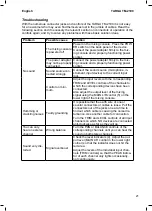
Troubleshooting
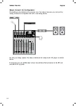
With the numerous connector jacks and controls of the TARGA TM-2100 it is not easy
for a newcomer who may even find themselves lost in the jumble of cables. Read the
following section and if necessary the relevant section on connectors or operation of the
controls again, and try to solve any problems with these basic solution ideas.
Problem
Possible cause
Solution
No sound
The mixing console
is powered off.
Power on the mixing console. Press the POW-
ER switch on the back panel of the device.
Connect the power adapter firmly to the mix
-
ing console and a properly-functioning power
socket.
The power adapter
may not be properly
connected.
Connect the power adapter firmly to the mix
-
ing console and a properly-functioning power
socket.
Sound source con-
nected wrongly.
Connect the sound source (microphone, in
-
strument, input device) to the correct input
jack.
Control on mini
-
mum.
Adjust the input levels with the corresponding
TRIM and LEVEL controls of the channels to
which the corresponding devices have been
connected.
Also adjust the output level of the mixing
signal using the MAIN L/R control (5) on the
lower right of the mixing console.
Humming or
crackling noises
Faulty grounding
It is possible that the earth wire of one or
several connectors or cables is loose. Pull the
connectors out of the jacks one at a time to
find out which cable is causing the noise dis
-
turbance. Use another cable for connection.
Turn the TRIM and LEVEL controls of all input
channels on which NO devices are connected
anti-clockwise as far as they will go.
You can only
hear one stereo
channel
Wrong balance
Turn the PAN or BALANCE controls of the
corresponding channels until you can hear the
sound on both stereo channels.
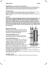
Sound very dis-
torted
Signal overboost
Check the level indicators (4). Adjust the out
-
put level (MAIN L/R control in the lower right
corner) so that the indicator does not hit the
red area.
Adjust the levels of the individual input chan-
nels (TRIM controls) so that the PEAK indica
-
tor of each channel only lights occasionally,
not continuously.