background image

1

2

3

4

5

6

7

8

3 – 11

T

HE

 Z

IP

/LS-120 M

ODULE


(

OPTION

)

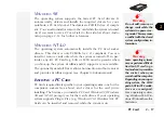
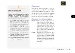
As mentioned on page 3 of this chapter, the Zip or LS-120 is 

hot-

removable

. However, there are some limitations (see “Opera-

tion”, page 3-13~14).

S

TARTUP

 C

ONSIDERATIONS

When you install the Zip or LS-120 drive, make sure the bay is

empty, then push the module in until its outer edge is flush with

the side of the computer. You should hear a “click” from the

locking latch on the bottom panel when the module is in place.
The Zip or LS-120 module must be installed 

before

 you boot-up.

If it isn’t in the Drive bay when the system boots, the system

won’t recognize it and won’t allocate system resources.

Note:

The Zip drive is not a “boot” device whereas LS-120 drive can

become bootable only if you activate its booting function in the

BIOS 

Setup

.

D

RIVE

 B

AY


WITH

 Z

IP

F

IG

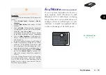
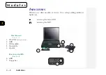
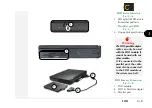
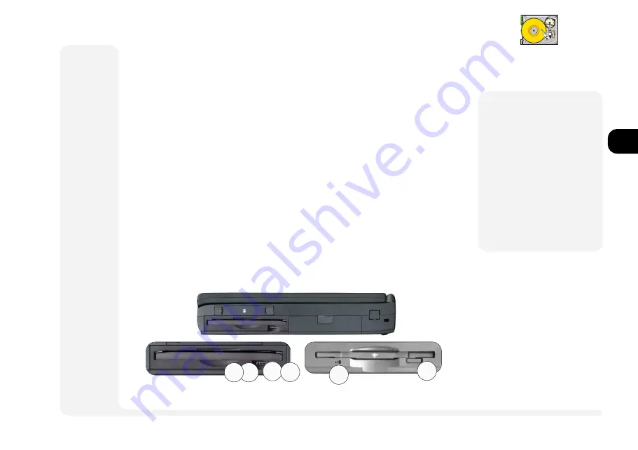
. 3 – 9

1. emergency eject

2. accessing LED (green)

Note:

 Swappable with

 LS-120

Zip/LS-120

M

Warning

Do not remove the Zip/

LS-120 module from the

Drive bay while it is ac-

tive. Disconnecting dur-

ing data access may crash

and/or damage the sys-

tem, the Zip/LS-120 or re-

sult in data loss and/or

corruption.

1

2

ñ

1

ñ

2

ZIP

LS-120

Summary of Contents for TN700

Page 1: ...1 2 3 4 5 6 7 8 i MULTIMEDIA NOTEBOOK COMPUTER USER S MANUAL...

Page 2: ...nd or registered trademarks of their respective companies They are mentioned for identification purposes only and are not intended as an endorsement of that product or its manufacturer Third Edition A...

Page 3: ...ular installation If this equipment does cause harmful interference to radio or television reception which can be determined by turning the equipment off and on the user is encouraged to try to correc...

Page 4: ...d damage your data 4 Keep it dry This is an electrical appliance If water or any other liquid gets into it the computer could be badly damaged 5 Be careful with power The computer has specific power r...

Page 5: ...ren away from and promptly dispose of a damaged battery Always dispose of batteries carefully Batteries may explode or leak if exposed to fire or improperly handled or discarded M Attention The produc...

Page 6: ...ty and expose you and the computer to electric shock Refer all servicing to authorized service per sonnel Unplug the computer from the power supply Then refer servicing to qualified service personnel...

Page 7: ...s Looks at the removable devices in the HDD Drive and Power bays Chapter 4 Firmware Is about the notebook s built in software the POST and Setup utilities Chapter 5 Power Examines the power system bot...

Page 8: ...Enter programs operating systems italics Setup Windows 95 files all capitals AUTOEXEC BAT program groups bold Control Panel sequences arrows My Computer Control Panel icons user interface switches bol...

Page 9: ...g vi Servicing vi About This Manual vii Conventions viii Chapter 1 Introduction Packing Contents 1 3 Quick Start 1 3 System Map 1 4 Front View Work Panel LCD CD ROM Bay 1 4 Left View Reset IrDA USB Au...

Page 10: ...2 6 Inserting Removing a CD ROM 2 6 Multimedia Applications 2 7 MPEG 2 7 Audio CDs 2 7 Video 2 8 Setup 2 9 LCD 2 9 Attaching a Monitor 2 10 TV 2 11 Switching 2 12 Audio 2 13 Additional Audio 2 14 PC C...

Page 11: ...for the First Time 3 6 Drive Bay Modules 3 7 Removing a Module 3 7 Securing a Module 3 7 FDD Floppy Module 3 8 Startup Considerations 3 8 Drive Bay Installation 3 8 Parallel Connection 3 8 Inserting R...

Page 12: ...4 9 Parallel Port Components Menu 4 9 PS 2 Mouse Port Components Menu 4 9 Power Saving 4 10 Enable Power Saving Power Menu 4 10 Customize Power Menu 4 11 Suspend Controls Power Menu 4 11 Resume Timer...

Page 13: ...CardWizard 6 4 CardWizard Operating Systems 6 4 CardWizard Windows NT 4 0 6 5 Using Card Wizard 6 5 Power Management 6 6 Using Removable Storage Cards 6 6 CardWizard Utilities 6 6 Supported PC Cards Z...

Page 14: ...ers 2 6 Windows 95 2 6 Windows NT 4 0 2 6 Windows 3 51 2 6 OS 2 Warp 2 6 DOS Windows 3 1x 2 6 More on Video Displays 2 8 Video Setup 2 8 Windows 95 2 8 Windows NT 4 0 2 9 Display Properties Control 2...

Page 15: ...10 Additional Power Management 5 13 Installing SystemSoft PowerProfiler 5 14 Installing DIMMs 6 3 Installing CardWizard 6 4 Windows 95 6 4 Windows NT 4 0 6 5 Formatting in Windows NT 4 0 6 6 Installin...

Page 16: ...ig 2 8 Display Panel TV Settings 2 11 Fig 2 9 Audio Subsystem Ports 2 13 Fig 2 10 PC Card Sockets 2 15 Fig 2 11 Fax Modem Port 2 19 Fig 3 1 Drive Modules 3 2 Fig 3 2 Drive Indicator LEDs 3 2 Fig 3 3 R...

Page 17: ...ack 5 7 Fig 5 4 PowerProfiler 5 15 Fig 6 1 Inserting the DIMM 6 3 Fig 6 2 Mouse Properties 6 12 List of Tables Table 1 1 Hot Key Controls 1 11 Table 1 2 LED Indicators 1 12 13 Table 2 1 Video Output K...

Page 18: ...1 2 3 4 5 6 7 8 xviii P r e f a c e NOTES...

Page 19: ...uded but in a sepa rate section Depending on how your system is configured some or all of the features described may already be set up If you re an advanced user you may want to skip over most of this...

Page 20: ...eface Operating systems i e Windows 95 Windows NT 4 0 OS 2 Warp UNIX etc have their own manuals as do application software e g word processing and database programs If you have questions about those p...

Page 21: ...Remove all packing materials floppy disks and any PC Cards 3 Secure the main battery pack in its compartment Ch 5 4 Securely attach any peripherals you want to use with the notebook i e mouse or keyb...

Page 22: ...notebook cover slide this latch to the right TouchPad Chapter 2 System covers basic functions WORK PANEL VIEW FIG 1 2 1 microphone 2 speakers 3 close cover switch 4 power button 5 power on light 6 st...

Page 23: ...this port is going to work with USB Refer to Chapter 2 System on how to activate this port Audio Setup for this subsystem is covered in Chapter 2 System PC Card Your computer uses newer technologies t...

Page 24: ...em doesn t have a fax modem installed this slot will have a cover Do not remove it Ask your dealer about in stalling a fax modem module not immediately available M Warning Don t try to remove the hard...

Page 25: ...M Warning The default setting in Setup makes all ports hot Depending on the peripheral this could cause a problem when you attach it Check your peripheral s manual be fore you make a connec tion REAR...

Page 26: ...2 System Expansion Port With the main hinged door closed connect to this port through the sliding door The op tional docking station s manual has more information Parallel Port This port supports seve...

Page 27: ...M1 serial Use this with any 9 pin serial device e g a mouse serial printer or modem Consult the user s guides for the device this port is going to work with For pointing devices refer to Chapter 2 Sys...

Page 28: ...iolate your warranty M Warning Follow the safety in structions for using modules BOTTOM PANEL FIG 1 7 1 Drive bay expansion module release latch 2 CPU compartment fan 3 PPGA CPU view 4 MMO CPU view Th...

Page 29: ...eo setup information Fn F10 suspend switch activates Suspend to Disk if that feature is enabled toggles between suspend function on off Suspend To RAM only Ctrl Alt S enter Setup If pressed immediatel...

Page 30: ...e t s y s g n i h s a l f M A R o t d n e p s u S r a B r e w o P s e t a t s l l a N O n O m e t s y s M A R o t d n e p s u S y b d n a t S e z o D t h g i l o n F F O m e t s y s k s i D o t d n e...

Page 31: ...H g n i s s e c c a k c o L m u N d e t a v i t c a d a p y e k c i r e m u n d e d d e b m e d e g a g n e s i k c o L m u N k c o L s p a C e s a c r e p p u e r a s y e k c i t e b a h p l a l l a...

Page 32: ...1 2 3 4 5 6 7 8 1 14 Introduction NOTES notes...

Page 33: ...stem and chipset are in Chapter 6 Enhancements The driver setup information described in this chapter assumes the software is located on a CD ROM identified as drive D If the driver is available from...

Page 34: ...hould consult those manuals Hot Keys These keys and combinations control some of the hardware Refer to page 1 11 TYPE KEYS FIG 2 1 The embedded numeric keypad outlined is ac tivated by pressing NumLoc...

Page 35: ...key you will still need to use the notebook s keyboard This port can only accept one type of device configuration per system ses sion For example if you connect a PS 2 mouse to this port you cannot co...

Page 36: ...The system automatically enables the built in TouchPad If you re using any version of Windows or OS 2 you don t have to install a driver for it If you want to use the TouchPad s ad vanced features re...

Page 37: ...h and re connect the same device dur ing a system session TouchPad Serial Device Windows 9x Windows NT 4 0 1 Attach the serial device when the system is off 2 Turn on the system and allow the operatin...

Page 38: ...vers WINDOWS 9X WINDOWS NT 4 0 WINDOWS NT 3 51 OS 2 WARP These operating systems automatically detect and configure an installed CD ROM module DOS WINDOWS 3 1X If you re using one of these operating s...

Page 39: ...lower PC Card socket supports a ZV card This card works with the CD ROM and video subsystems to pro duce better quality images However to use it you must in stall these drivers The CD ROM driver cover...

Page 40: ...WS 9X To setup the Windows 9x video driver and utilities 1 Open Control Panel Display 2 Click on Settings Advanced Properties Adapter or Settings Advanced Adapter 3 Click on the Change button For Wind...

Page 41: ...t necessary M Warning Do not allow any foreign objects i e paper or plastic to get between the lid LCDandthework panel They could dam age or scratch the LCD and or accidentally ac tivate the close co...

Page 42: ...h rate for VGA moni tors without drivers is 60Hz For NTSC and PAL TVs it s fixed at 60Hz and 50Hz respec tively Video Setup cont The S3 driver adds an additional page to Display Properties This has cu...

Page 43: ...idebar for details and the driver is configured for your TV s standard NTSC or PAL use the video driver control panel Note The default refresh rate for NTSC and PAL TVs is fixed at 60Hz and 50Hz respe...

Page 44: ...r e f f i d r o e m a s l o r t n o C l a u D C S T N 0 8 4 x 0 4 6 r o t i n o m D C L D C L r o t i n o m V T D C L V T D C L s i V T C S T N r o f n o i t u l o s e r e h T D C L e h t r e v e w o...

Page 45: ...ogram s dialog boxes When asked for Driver Disk in sert the Drivers Utilities CD ROM then click on OK then on Browse and navigate to D drivers win95 audio Click OK twice to allow the wizard to install...

Page 46: ...mpying CD ROM To install 1 Open Control Panel System Device Manager 2 Click on Sound video and game control lers and choose ES1879 Control Interface 3 Click on Properties Driver Update Driver button t...

Page 47: ...ard for more information about its capabilities and how to use its features PC CARD SOCKETS FIG 2 10 1 socket 0 lower eject button 2 socket 1 upper eject button Audio Setup cont WINDOWS NT4 0 To insta...

Page 48: ...ents are newer than the drivers supplied by Windows 95 so before you can use this device you must make some changes to your system 1 Open Control Panel System Device Manager Other devices Remove the P...

Page 49: ...I O forPCCardde vices are reassigned Some operating systems e g Windows 95 Win dows 98 do not have this limitation WINDOWS NT 4 0 The operating system automatically installs the PC Card socket drivers...

Page 50: ...de scribed in the side bar Once your system is setup you should refer to the USB devices manuals on how to operate them USB and Related Chipset Setup for Windows 95 Enabling the USB features is a two...

Page 51: ...CD ROM and click on Next If Windows 98 you need to choose Search for the best driver for your devive then Next 4 Click on Other Locations if Windows 95 Choose Specify a location If Windows 98 and navi...

Page 52: ...folder on the SP3 CD ROM Highlight PnPISA inf then click right mouse button and choose Install When prompted close any other applications and al low to restart 4 After system resumes the Add New Hard...

Page 53: ...ith the system differently and so requires different setups Drivers Other Considerations If your dealer hasn t done so you must set up both HDD and Zip drives before they can be used for the first tim...

Page 54: ...er a data module is in use the corresponding indicator lights up accessing the main HDD accessing the FDD DRIVE MODULES FIG 3 1 1 CD ROM see Chapter 2 System 2 HDD 3 FDD module 4 Zip module 5 Zip disk...

Page 55: ...hot swapping is not recommended If possible turn the system off before making any swaps Hot swapping a module risks accidentally crashing the machine and losing unsaved data or damaging a module if it...

Page 56: ...each other The HDD bay handle will pop out 2 Gently grasp the HDD cartridge handle and pull it out REMOVING THE HDD FIG 3 3 1 slide the HDD latches towards each other 2 pull the cartridge out INSTALLI...

Page 57: ...ectronic component side with the mylar shield 4 Insert the HDD and shield combination into the frame electronic side up As you do so carefully fit the edges of the shield around the screw holes of the...

Page 58: ...o do this To format use the utility from your operating system e g MS DOS s for mat or format s command Consult your oper ating system s manual for more information on its partitioning and formatting...

Page 59: ...e we recommend making any changes with the system turned OFF To release a module 1 Slide the locking latch on the bottom part of the module to the unlock position and hold it 2 Grasp the edge of the m...

Page 60: ...module in until its outer edge is flush with the side of the computer You should hear a click from the locking latch on the bottom panel when the module is in place PARALLEL CONNECTION If the Drive b...

Page 61: ...s connected to the parallel port the cable must also be connected to the FDD module or the system may halt FDD STATUS INDICATOR FIG 3 6 1 LED lights for FDD access from either position DRIVE BAY WITH...

Page 62: ...extreme temperatures These conditions can damage your data It s also a good idea to make backup copies of software and data If a disk label is already on the disk use a soft tipped pen to write on the...

Page 63: ...ace The Zip or LS 120 module must be installed before you boot up If it isn t in the Drive bay when the system boots the system won t recognize it and won t allocate system resources Note The Zip driv...

Page 64: ...to one letter Zip Tools Installation WINDOWS 9X WINDOWS NT 4 0 Make sure the Zip drive is installed before you turn on the computer When the operating system starts up it automati cally detects and as...

Page 65: ...Tools Installation WINDOWS 9X WINDOWS NT 4 0 Make sure the LS 120 drive is installed before you turn on the computer When the operating system starts up it automati cally detects and recognizes the L...

Page 66: ...ecommend reviewing Iomega Tools for Windows NT s on line help Zip LS 120 Zip LS 120 Installation cont for Fixing CD ROM Letter WINDOWS 9X To fix the CD ROM s new letter assignment so that it stays the...

Page 67: ...should review this chapter first and note the original settings found in Setup Even if you are a beginner keep a record of the settings you find and any changes you make This information could be use...

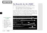
Page 68: ...OST FIG 4 1 1 BIOS information 2 CPU type 3 main memory status 4 error notice 5 IDE including HDD identification notice 6 pause indicator only appears if there is an error SystemSoft BIOS for Intel 43...

Page 69: ...ossible Non Fatal Errors This kind of error still allows you to boot You will get a message identifying the problem make a note of this message followed by the cue Ctrl Alt S to enter System Configura...

Page 70: ...ING SETUP To enter Setup turn on the computer and press Ctrl Alt S during the POST The prompt seen in Fig 4 1 is usually present for a few seconds after you turn on the system If you get a Keyboard Er...

Page 71: ...ar with five 5 menu headings When you select the heading of a menu its list appears Use these menus to make any changes The help box along the bottom of the screen has useful messages about the menus...

Page 72: ...setting if the Expand mode greatly distorts the images TV SETUP STARTUP MENU Enable TV This switch allows you to use the FN F9 hot key toggle between displays If you start up in TV only you can use th...

Page 73: ...first and leave the new password fields blank The User password won t be effective until you enable one of the options after the verification area This restricts user access to the system Pass word to...

Page 74: ...tion To format a disk in the NEC format how ever your operating system must also support it A Word about HDDs Setup auto detects Hard Drive C and lists it in the system summary see page 4 5 The system...

Page 75: ...you are connecting to the optional docking station choose Se rial to use the 2nd serial port on that device PARALLEL PORT COMPONENTS MENU There are several modes available Standard AT Centronics Bidir...

Page 76: ...file transfers that are visible on screen or a screen saver Disabled the power saving schemes monitor for system activity except the screen This setting may also be necessary for some operating system...

Page 77: ...eout see the Customize submenu has started M Warning If you haven t set up the system for Suspend to Disk or if the space re served for the Suspend to Disk partition isn t large enough the system will...

Page 78: ...1 2 3 4 5 6 7 8 4 12 F i r m w a r e notes NOTES...

Page 79: ...tery management utilities The first part covers the battery ies and the AC adapter To see where these fit into the system review the system layout in Chapter 1 Introduction The second part is about th...

Page 80: ...a l f M A R o t d n e p s u S r a B r e w o P s e t a t s l l a N O n O m e t s y s M A R o t d n e p s u S y b d n a t S e z o D t h g i l o n F F O m e t s y s k s i D o t d n e p s u S r e w o p C...

Page 81: ...teady between 100 and 240 volts When the adapter is connected to a power source and then to the computer the icon on the LED panel lights to indicate the system is receiving AC power To use the AC ada...

Page 82: ...ollow this procedure regardless of whether or not the AC power source is plugged in during the battery inactivity 1 Install the battery in its compartment if it s not already there 2 Make sure that th...

Page 83: ...wer source to recharge the battery Leave the system off while charging The battery status icon stays red during charging When the battery is full the light turns green The approximate charge time is a...

Page 84: ...n the system Put the system in Suspend mode and make sure power is available from the Power bay or the external adapter module INTO THE POWER BAY Note The battery pack is packaged separately from the...

Page 85: ...d in the Drive bay with the module latch on the bottom of the computer and a latch on the pallet s front 1 Angle the battery into the battery frame 2 Unlock the drive module FDD or Zip and slide it ou...

Page 86: ...he AC adapter or with a 2nd battery present Go into Suspend to RAM Load a 2nd battery When the system receives AC power the LED glows and the battery status LED s displays a steady red light to indica...

Page 87: ...system enters the selected mode three minutes after the warning starts if you haven t given the system more power If either of these options starts the battery should be considered fully depleted thou...

Page 88: ...Disk it makes use of a special partition on the HDD This is created and managed by the 0VMAKFIL utility The Suspend to Disk partition must be setup before you install the operating system For this rea...

Page 89: ...artition type a 0VMAKFIL P13 Enter Note Since this method requires you to configure your HDD you should make your Suspend to Disk partition large enough to accommodate the largest amount of memory you...

Page 90: ...Fn F10 again Alarm Resume The clock reaches the time set for the Alarm Resume feature in Setup Ring in The system will wake if a ring in is detected from the optional built in Fax Modem a PC Card Fax...

Page 91: ...cess APM For best results leave it set to Advanced For more information about APM re fer to your operating system documen tation Additional Power Management You can conserve power by reducing the amou...

Page 92: ...ws NT Once activated a small battery icon ap pears on the right bottom corner of your screen You can use this icon to invoke PowerProfiler or to put the system in Suspend Installing SystemSoft PowerPr...

Page 93: ...you make any purchases The PC Card driver is not needed for most Windows 95 users However Windows NT 4 0 users will find it very useful The ZV Port drivers are required if you plan on using the PC Ca...

Page 94: ...socket or in both sockets in any order and any size combination Socket requirements 16MB 32MB or 64MB module size 144 pins EDO or SDRAM type S O DIMMs 3 3 volt TSOP package Rated at 60ns or faster Ma...

Page 95: ...es on the sides of the module allow you to insert it only one way Make sure it is seated as far into the slot as it will go 6 Gently push down on the module until its lock catches snap into place DO N...

Page 96: ...erwise 5 Choose Typical to enable the slots for all types of cards this will use more system resources Choose Custom if you know that you won t need some features When asked for insert disk 2 or inser...

Page 97: ...Program Files directory on your C drive unless you choose otherwise 5 When the installation is complete allow the system to reboot to complete the setup CARDWIZARD WINDOWS NT 4 0 On its own Windows N...

Page 98: ...ms To use it copy the CS_APM EXE file from the Drivers Utili ties CD ROM to the CardWizard directory on your HDD Then using an editor pro gram modify the CONFIG SYS file install drive path cs_apm exe...

Page 99: ...PC Card socket 2 Switch to the CARDWIZ directory or the directory where you installed the CardWizard software 3 Type atainit drive letter and press Enter e g atainit e Enter Follow the prompts on the...

Page 100: ...th all legacy cards It also extends ZV card support to Windows 3 1x and Windows 95 We recommend you read the readme file on the CardWizard disk to find out if any special conditions apply to a card yo...

Page 101: ...e Ports COM LPT Next Have Disk Browse Insert the Drivers Utilities CD ROM and navigate to d drivers win95 irda fir_smc When prompted choose SMC IrCC Fast Infrared Hardware and Driver from Model list I...

Page 102: ...move Programs utility in the Control Panel 3 Click on Install then Next Click on Browse and navigate to D drivers win95 audio audrack setup exe if Windows 95 D drivers nt40 audio audrack setup exe if...

Page 103: ...gestures TouchPad TABLE 6 1 DEFAULAT TOUCHPAD GESTURES The MouseWare driver supports both Logitech and Standard gestures LOGITECH GESTURE STANDARD GESTURE DESCRIPTION E QUIVALENCE e d i l S e d i l S...

Page 104: ...w 95 use the Buttons tab in Mouse Properties of Control Panel 1 From the Start menu select Settings Control Panel 2 Double click on the Mouse icon When the Mouse Properties page appears use the on lin...

Page 105: ...ations The information listed in this section is for reference only It is subject to change at the manufacturer s discretion and without notice Unless otherwise indicated none of the components and or...

Page 106: ...at 2 5V is the most energy efficient though the slowest However actual power consumption also depends on the amount of work the CPU must perform PACKAGING The MMO Mobile Module Operation pack age com...

Page 107: ...2 cache 512KB Pipeline Burst SRAM RAM base 0MB EDO 3 3V RAM expansion 128MB maximum using one or both sockets Socket 1 Socket 2 requirements 16MB 32MB or 64MB modules 144 pins 3 3 volt TSOP package ED...

Page 108: ...C TV VGA 640 x 480 all LCDs and monitors SVGA 800 x 600 LCDs monitors PALTVs XGA 1024 x 768 LCDs monitors SXGA 1280 x 1024 monitors s r o l o C n o i t u l o s e R A G V A G V S A G X A G X S y a l p...

Page 109: ...Line in Mic in Headphone speakers out DRIVES Factory Installed Modules 24X or faster CD ROM or 2X DVD HDD Bay Module 2 5 12 7mm removable 2 1GB or larger Drive Bay Modules 3 5 1 44MB FDD 3 mode switch...

Page 110: ...eft NiMH batteries charge at a constantrate Li Ionbatteries charge rate slows for about the last 25 More on Charging Your system doesn t require a proprietary bat tery so to accomodate the widest rang...

Page 111: ...yboard PC Card 2x Type II or 1x Type III PC Card with ZV support Expansion proprietary docking station 176 pin PCI local bus Not immediately available OTHER FEATURES TouchPad built in PS 2 pointing de...

Page 112: ...e 24X CD ROM or DVD module 2nd battery module switchable with FDD ZIP module switchable with FDD LS 120 module switchable with FDD Drivers Utilities Expansion DRAM module s 16MB 32MB or 64MB Battery p...

Page 113: ...ed the safety precautions in the preface If all else fails talk to your dealer You should also make a record of what happened and what remedies you tried Of course if something goes wrong it will happ...

Page 114: ...eck if the adapter is connected to a power cord and then to the DC in socket on the computer s rear panel Make sure the power cord is plugged into a wall outlet possible cause Battery missing incorrec...

Page 115: ...system is using too much power indicator The battery status icon or is moving from green to red too quickly solution Go into Setup see Chapter 4 Firmware and adjust the controls available in the Power...

Page 116: ...argeable batteries avail able for this computer are manufactured to exact stan dards so the problem may be in your environment Heavy air pollution moisture and other contaminants may make battery lead...

Page 117: ...tion Turn the system off and then on again to reboot the sys tem If it still doesn t work connect the AC power and try again Leave the computer attached to AC power so that the battery has a chance to...

Page 118: ...ons see Chap ter 1 Introduction Hot Key Controls possible cause The viewing angle of the LCD is bad indicator The screen appears shiny or too dim solution Adjust the position of the LCD LCDs are desig...

Page 119: ...hard disk solutions a The BIOS usually automatically detects the parameters of the hard disk However it may occasionally detect a different set of parameters If the system cannot use the hard disk ch...

Page 120: ...ort since you will lose any unsaved data try to reboot the system or if that doesn t work turn the computer off and on again possible cause The system cannot access the Suspend to Disk partition indic...

Page 121: ...nt hard disk with a Suspend to DiskpartitiononitortherehasbeenaCMOSorChecksum failure You must run the 0VMAKFILutility after one of the above conditions The system never goes into Suspend mode possibl...

Page 122: ...B 10 The PC Card does not work possible cause The drivers are not loaded indicator The system cannot access the card after it is installed solution Load the proper drivers see Chapter 2 System and Ch...

Page 123: ...ay speci fying the error You can press F1 to try to continue the boot process or press F2 to run Setup If the following messages occur press F2 to run Setup message Diskette drive A error description...

Page 124: ...s socket s refer to Chapter 6 Enhancements 2 Run Setup to allow the system to recheck the amount of memory present then save the Setup information and reboot refer to Chapter 4 Firmware 3 Turn off the...

Page 125: ...ave to replace the external keyboard 3 If you changed the video output make sure you didn t dislodge the keyboard ribbon connectors refer to Chapter 2 System 4 If the problem persists contact your ser...

Page 126: ...update its record refer to Chapter 4 Firmware message Operating system not found description The operating system can t be found on either drive A or drive C solution 1 Assuming there is an operating...

Page 127: ...all the settings are correct message Real time clock error description The real time clock failed the BIOS test solution Contact your service representative The onboard battery may have to be replace...

Page 128: ...ksum bad run Setup description The system CMOS has been corrupted or modified incorrectly solution Run Setup and reconfigure the system Note This may indicate the CMOS was targeted by a virus Reboot f...

Page 129: ...equip ment 2 A printed circuit board that connects a system board to a peripheral I O device devices or adds specialized func tions to the system Address An identification such as a label number or n...

Page 130: ...BIOS An acronym for Basic Input Output System The program that customizes a computer Boot Derives from bootstrap To start or restart a computer system by reading instructions from a storage device in...

Page 131: ...on An assembly of machines that are interconnected and are pro grammed to operate as a system The layout or design of ele ments in a hardware or information processing system CPU Central Processing Un...

Page 132: ...from a particular peripheral device The electrical and mechanical requirements are different from one kind of device to another so software drivers are used to standardize the format of data between...

Page 133: ...isk con troller External devices usually use SCSI controllers Internal option A part installed inside the system unit cover which enhances operation of the system such as an adapter and a memory chip...

Page 134: ...levels but no visibility in low illumination levels Load In programming enter data into storage or working registers M N MB Megabyte 1 048 576 bytes 1024KB Memory The storage facilities of the comput...

Page 135: ...A video and audio compres sion standard which allows decompression at 1 2 MB to 1 5 MB second so CD players can replay color movies at a realis tic 30 frames second NTSC National Television Standards...

Page 136: ...ht wires Additional wires are needed to exchange control signals Parameter An arbitrary constant A variable in an algebraic expression that temporarily assumes the properties of a constant PC Card Thi...

Page 137: ...provides PCMCIA support which automati cally recognizes when PCMCIA devices are inserted and re moved The simpler term PC Card has largely replaced this acronym to refer to these cards PnP Plug and P...

Page 138: ...idered to be superior to SLIP because it features error detection data compression and other elements of modern communications protocols that SLIP lacks Q R RAM Random Access Memory Memory into which...

Page 139: ...ual computing units the arrangement of interconnections be tween the units and the adjustments needed for the com puter to operate 3 The preparation of a computing system to perform a job or job step...

Page 140: ...aphics Adapter Video system that allows simulta neous display of 256 colors at 640 x 480 graphics resolution and 720 x 400 text resolution This standard has been superceded by SVGA 256 colors at 800 x...

Page 141: ...section are for reference only 3 Mode See FDD A AC adapter See Power AdLib See Audio APM See Power Audio 1 5 2 1 2 13 2 15 controller See Chipset driver See Operating System ESS AudioDrive 2 13 2 14 m...

Page 142: ...3 1 3 3 5 6 See also Power Beep 2 17 6 5 6 6 Bidirectional mode See Peripherals printers BIOS See Firmware BIOS Setup utility See also Chipset BIOS Boot boot up 1 11 4 3 5 4 5 5 See also Starting Bri...

Page 143: ...DIMM RAM See Options memory RAM Display 1 4 2 1 2 15 4 4 See also Chipset VGA display driver See Operating System external monitor 2 8 A 4 LCD 1 3 1 11 2 8 2 9 A 4 See also Ports TFT 1 11 resolution...

Page 144: ...rts parallel F Fan 1 5 1 10 Fax Modem 5 12 FDD 1 3 1 6 3 10 formatting 5 11 module 1 8 Firmware 5 10 BIOS Setup utility 1 11 3 1 4 1 4 2 4 3 4 4 4 5 5 1 5 5 6 3 Item Specific Help 4 5 POST 4 1 4 2 4 3...

Page 145: ...ing System OS 2 Warp Intel See Options CPU See also Chipset IrDA port See Ports Item Specific Help See Firmware K Kensington lock See Security Keyboard 1 3 1 4 1 8 1 11 2 1 2 2 2 5 See also LED combin...

Page 146: ...so Power CapsLock See also Keyboard charging See also Power drive bay See also Bays drive floppy bay 3 2 See also Bays floppy HDD bay 3 2 See also Bays HDD NumLock See also Keyboard PC Card See also P...

Page 147: ...2 3 3 3 4 See also HDD HDD module replacing upgrading 3 5 3 6 MO 3 11 See also MO magneto optical drive removing 3 7 Swap See also Hot Swapping Mouse 1 3 1 8 1 9 2 3 mouse 2 3 See also Peripherals Mic...

Page 148: ...3 13 PC Card setup driver 2 16 2 17 6 4 TouchPad setup driver 2 4 2 5 video setup driver 2 8 2 9 Windows NT 4 0 1 2 6 1 audio setup driver 2 14 driver setup See also Software utility MO setup driver 3...

Page 149: ...sh cards 6 7 I O 2 17 LAN 2 17 SCSI 2 17 removing 2 17 SRAM ATA drives 6 4 6 6 6 7 Type II 2 15 Type III 2 15 ZV type 1 5 2 15 2 16 2 17 6 1 6 8 See also Multimedia VPM driver 6 8 PCMCIA See PC Card P...

Page 150: ...7 2 4 2 5 5 12 2nd 1 5 See also Firmware BIOS Setup utility POST See Firmware Power iv 1 4 adapter iv 1 3 5 1 5 3 5 4 external 5 6 battery v 1 3 1 6 3 3 5 1 5 3 5 4 5 7 charging 1 3 discharging 5 4 5...

Page 151: ...2 4 2 5 6 4 S S DSTN See Display S TFT See Display LCD S VGA See Display S VGA Safety 1 2 1 3 5 4 Security 5 11 5 12 access restrictions 4 7 hardware Kensington Lock 1 8 password 5 12 Serial See Ports...

Page 152: ...mode See Firmware See also Peripherals Standby mode See Power management Starting 1 3 5 11 See also Quick Start Status panel 1 4 Storage 1 3 Swapping 3 3 See also Module cold 3 3 hot 3 3 hot removabl...

Page 153: ...tivity 4 10 W Warning 1 2 1 5 1 6 1 10 2 9 2 10 2 11 2 13 2 17 3 5 3 8 3 9 3 11 4 11 5 3 5 7 5 10 5 11 6 2 6 3 symbol 1 2 Warnings iii v Warranty 6 2 Wavetable See Audio Windows 3 1x See Operating Sys...

Page 154: ...I I n d e x I 3 4 5 6 A 8 I 14 C X X TFT See Display X VGA See Display X VGA Z ZV type PC Card See PC Card xt zv...

Reviews: