

11
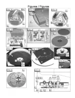
Parts Identification:
A.
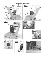
Front Shield [FIG. 1].
B.
Front Shield Bolts [FIG. 1, FIG. 3].
C.
Adjustable Handle [FIG. 1].
D.
Handle Bolts [FIG. 1].
E.
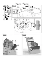
Axle In Transport Position [FIG. 11].
F.
Axle In Operation Position [FIG. 11].
G.
Axle Stop Bolt [FIG. 11, FIG. 30].
H.
Electrical ON / OFF Switch (Electric Model Only)
[FIG. 6].
I. ------
J.
Voltage Change Switch (Electrical Model Only)
[FIG. 5].
K.
Reset Button (Electrical Model Only) [FIG. 4].
L.
Throttle Lever (Gasoline Model Only) [FIG. 10].
M.
Engine STOP Position (Gasoline Model Only)
[FIG. 10].
N.
Engine START Position (Gasoline Model Only)
[FIG. 10].
O.
Engine Choke (Gasoline Model Only) [FIG. 10].
P.
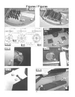
Accessory Disks [FIG. 20, FIG. 14, FIG. 15, FIG.
16].
Q.
Multi-Segmented Diamond Disks [FIG. 24, FIG.
25].
R.
Diamond Disk Adapter [FIG. 25].
S.
Diamond Disk Attaching Hardware [FIG. 25].
S1. Flat Head Screws.
S2. Locknuts.
T.
Diamond Disk Adapter Attaching Hardware [FIG.
25].
T1. Capscrew, 3/8-16UNC x 1-1/2” Long.
T2. Lockwasher 3/8”, Split Type.
T3. Washer, .3/8 SAE.
U.
Wooden Wedges [FIG. 14, FIG. 15, FIG. 16].
V.
Wrench, ½” (13 mm) x ¾” (19 mm) [FIG. 8]
V1. Wrench Can Be Used On Items Marked “V1”
[FIG 2, FIG. 3, FIG 20].
W. Lifting Eye (Electrical Model Only) [FIG. W].
X.
Tool Storage Area: Holds 6 Extra 2 x 2 x 4” Tools
[GG], & 9 Extra Wooden Wedges [U]. [FIG. 33].
Y.
Lifting Bail – Standard Equipment for Gas Model.
Z.
Weight Tray (FIG. 12)
AA. Weight Tray Hardware – With Optional Weight Kit
[FIG. 12]
BB. Weight Box – With Optional Weight Kit [FIG. 12]
CC. Hold Down Bolts (Weight Box) [FIG. 12].
DD. Weight Bar [FIG. 12].
EE. Weight Bar Attaching Hardware [FIG. 12].
FF. Lifting Handles [FIG. 1].
GG. Tool (2 x 2 x 4” Type):
GG1. Grinding Block [FIG. 14].
GG2. Tungsten Carbide Segment Block [FIG. 16].
GG3. Diamond Blocks [FIG. 15].
GG4. Wire Brushes [FIG. 26].
GG5. Scarifier Wheels [FIG. 27].
GG5A. Star Wheel [FIG. 28].
GG5B. Beam Wheel [FIG. 28].
GG5C. Tungsten Carbide Wheel [FIG. 28].
HH. Tool Holding Pad [FIG. 19, FIG. 20, FIG. 21].
II. ------
JJ. Scrubbing Pad [FIG. 19].
KK. ------
LL. Electrical Plug [FIG. 1].
MM. Ground Fault Circuit Interrupter (GFCI) [FIG. 7].
NN. Engine “Fast” Speed (Gas Model Only) [FIG. 10].
OO. ------
PP. Gearbox Cover [FIG. 2].
QQ. Water Tank Kit [FIG. 2].
QQ1. Tank with Lid [FIG. 1].
QQ2. Water Tank [FIG. 1].
QQ3. Water Tank Bracket [FIG. 1].
QQ4. Hose Clamps [FIG. 1].
RR. Lubrication Points:
RR1. Spindle Bearings [Six (6) Places] [FIG. 29].
RR2. Rear Wheels [FIG. 30].
RR3. Gearbox Grease Port [FIG. 29].
SS. Tool Holding Pad Attaching Hardware [FIG. 20,
FIG. 22, FIG. 25].
SS1. Capscrew, Hex Hd, .500-20UNC x 1.25”.
SS2. Lockwasher, .500”, Split Type.
TT. Voltage Change Lock Bolt [FIG. 5].
UU. Belt Tensioning Drawbolt [FIG. 32].
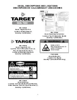
VV. Serial Number Plate [FIG. 13].
WW. Oil Drain Hose [FIG. 12, FIG. 13].
XX. Dust Port Cap [FIG. 31].
YY. Belt Tensioning Jam Nut [FIG. 32].
ZZ. Motor Platform Capscrews [FIG. 3].
AAA. Hose Port Cover [FIG. 31].
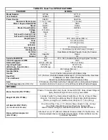
Summary of Contents for DT11H
Page 7: ...7...
Page 8: ...8...
Page 9: ...9...
Page 10: ...10...
Page 28: ...28 Diagram 1 Final Assembly Group 1 5 hp Electric...
Page 30: ...30 Diagram 2 Final Assembly Group 11 hp Honda Gas...
Page 32: ...32 Diagram 3 Handle Group 1 5 hp Electric...
Page 36: ...36 Diagram 5 Motor Group 1 5 hp Electric...
Page 38: ...38 Diagram 6 Engine Group 11 hp Honda...
Page 40: ...40 Diagram 7 Gearbox Assembly All Models...
Page 42: ...42 Diagram 8 Water Tank Kit Optional P N 177855 Complete Kit...
Page 50: ...50 Diagram 15 Wiring Diagram 1 5hp Electric Model...