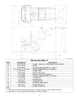
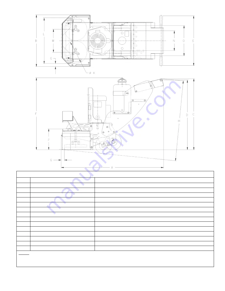
background image

 15


(DT15_dims.tif) 

Dimensions (Note 1) 

Item 

Length (cm) 

Description 

50.2” (127.5) 

Length – Maximum  (With Handle In Low Position) 

B 25.12” 

(63.8) 

Width 

37.6” (95.5) 

Operating Height (Maximum – Note 1) 

37.0” (94.0) – 31.5” (80.0) 

Handle Height (Maximum – Minimum) 

24.2” (61.5) 

Handle Width 

35.0” (88.9) 

Water Tank Height 

1.50” (3.8) 

Grind To Wall (Front and Side) 

41.9 (106.5) 

Transport Height (Maximum – Note 2) 

10.2” (25.8) 

Front Height 

11.0” (27.9) 

Disk Diameter 

22.2 (56.4) 

Grinding Width 

11.200 (28.45) 

Spindle Center Distance 

9.6” (24.4) 

Width Inside Tires 

14.6” (37.0) 

Width Outside Tires 

Notes: 


1.  Dimensions are for the machine with the axle in “operation” position unless otherwise specified. 
2.  Dimension “H” is for the machine with the axle in “Transport” position. 


Summary of Contents for DT11H

Page 1: ..._____________ Serial Number _______________ Engine Motor Serial No _______________ Purchase Date _______________ This Document Supersedes All Earlier Dated Documents 0A7796 August 16 2002 Printed in U...

Page 2: ...Spanish 7 10 Parts Identification English and Spanish 11 English Language Section SAFETY WARNINGS DO s DO NOT s 12 13 Specifications Power Sources 14 Unit Dimensions 15 Tool Application Guide 16 Pre...

Page 3: ...iangle Tri ngwulo De Advertencia Wear Eye Protection Usar Gafas De Protecci n Wear Head Protection Usar Casco De Protecci n Wear Breathing Protection Usar M scara De Protecci n The Use Of Ear Protecti...

Page 4: ...Peligroso Pay Extreme Attention To The Care And Protection Of The Machine Before Starting Up Ponga Extrema Atenci n Al Cuidado Y Preparaci n De La M quina Antes De Ponerla En Marcha Remove Tools From...

Page 5: ...IS MACHINE OPERATOR MAY BE EXPOSED TO A NOISE LEVEL EQUAL OR SUPERIOR TO 85 dB A ATENCION RIESGO DE DA O AUDITIVO EN CONDICIONES NORMALES DE UTILIZACI N EL OPERADOR DE ESTA M QUINA PUEDE ESTAR EXPUEST...

Page 6: ...on Top Of Adjustable Handle Quantity 1 All Models P N 189732 Decal Target LB 1 00 Location Front Of Gearbox Cover 1 Rear Of Adjustable Handle 1 Top RH of Adjustable Handle 1 Quantity 3 All Models P N...

Page 7: ...7...

Page 8: ...8...

Page 9: ...9...

Page 10: ...10...

Page 11: ...l Standard Equipment for Gas Model Z Weight Tray FIG 12 AA Weight Tray Hardware With Optional Weight Kit FIG 12 BB Weight Box With Optional Weight Kit FIG 12 CC Hold Down Bolts Weight Box FIG 12 DD We...

Page 12: ...nly in well ventilated areas DO instruct bystanders on where to stand while the machine is in operation DO establish a training program for all operators of this machine DO clear the work area of unne...

Page 13: ...vicinity of anything that is flammable Sparks could cause a fire or an explosion DO NOT operate this machine while under the influence of drugs or alcohol DO NOT operate this machine with any of the g...

Page 14: ...Rubber Grips Dust Port 3 0 76 2 mm Outside Diameter will accept 3 76mm Inside Dia Flex Hose Tires Wheels 8 Diameter Bore Semi Pneumatic Steel Wheel with Roller Bearings Grease Fitting Axle Diameter Z...

Page 15: ...5 0 88 9 Water Tank Height G 1 50 3 8 Grind To Wall Front and Side H 41 9 106 5 Transport Height Maximum Note 2 J 10 2 25 8 Front Height K 11 0 27 9 Disk Diameter L 22 2 56 4 Grinding Width M 11 200 2...

Page 16: ...s Scarifier Wheels FIG 27 FIG 28 See Current Product Catalog for Part Numbers of these Items Accessory Disk and Wooden Wedges Section 4 4 Remove Fiberglass Ice Oil Dry Foam Fill Packing Material Floor...

Page 17: ...tch set in the OFF position and disconnected from the power source before performing any maintenance Let the machine cool down 1 Check the engine air cleaner hose clamps Tighten as required 2 Tension...

Page 18: ...ter Nylon mesh Impregnated with Silicon Carbide For information contact your Dealer Depth of Cut Maximum See Section 4 Tool Installation Application Maximum material Size N A Nominal Operating Weight...

Page 19: ...anch circuit has two or more receptacles each receptacle has a maximum load ampere rating equal to 80 of the receptacle s rating When this machine is set up to operate on 115 VAC the motor has a full...

Page 20: ...than 20 degrees could cause severe engine damage and void your engine warranty 4 Tool Installation TOOL INSTALLATION 1 Rear Axle Position See FIG 11 Make sure the Axle is in the Transport Position E...

Page 21: ...n a complete kit P N 177823 FIG 17 that includes six steel blocks six tungsten carbide cutters hardware and tools and six wooden wedges A replacement cutter kit P N 177824 FIG 18 is also available It...

Page 22: ...g Pad HH See FIG 21 so that it mates with the triangular area on the Accessory Disk P b Use the 1 2 20UNF x 1 1 4 Long Capscrew SS1 and Lockwasher SS2 to attach the Tool Holding Pad to the Accessory D...

Page 23: ...level surface with the engine motor OFF and the start switch in the OFF position and the power source disconnected 1 If the engine or motor stops during operation check the following Electric Model a...

Page 24: ...2 or equal and should not require any lubrication until service work to the gears is required at 500 1000 hours Lubricate as required with Lubriplate Brand 630 2 or equal To inspect the inside of the...

Page 25: ...the Weight Box BB onto the Weight Tray Z 5 Use the Hold Down Bolts CC as a method to hold the Weight Box BB securely to the machine If the Hold Down Bolts CC are not used the Weight Box can be lifted...

Page 26: ...crew and Lockwasher that hold the Hose Clamp QQ 4 9 Install two 2 more Hose Clamps QQ 4 along the frame See FIG 1 10 Make sure the Water Valve QQ 1 is closed before adding any water to the water tank...

Page 27: ...ARTS LIST LISTA DE PIEZAS Parts List Callout Designation ITEM The Item Number Shown On The Diagram QTY The Quantity only at this location This the total quantity used throughout the entire diagram is...

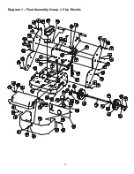
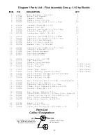
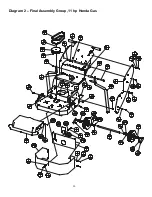
Page 28: ...28 Diagram 1 Final Assembly Group 1 5 hp Electric...

Page 29: ...p Dust Port 1 23 177801 Gearbox Cover Weldment 1 24 187051 Decal Dual Trac 3 Not Shown 25 052130 Decal Target 2 Not Shown 26 177857 Decal Oper Instr 1 Not Shown 27 176223 Decal Warning Guards In Place...

Page 30: ...30 Diagram 2 Final Assembly Group 11 hp Honda Gas...

Page 31: ...C x 25 2 19 139741 Capscrew Hex Hd M12 x 1 75 x 30mm 6 20 139742 Locknut Fiber M12 x 1 75 8 21 177946 Lift Bail 2 22 167631 Capscrew Hex Hd M12 x 1 75 x 100mm 2 23 166194 Spacer Lift Frame 2 24 020080...

Page 32: ...32 Diagram 3 Handle Group 1 5 hp Electric...

Page 33: ...nnector 312 Terminal Ring 2 15 167703 Wire Connector 25 Female Quick Connector 4 16 177885 Electrical Cord SO SOW 12 3 x 33 Inches 1 Parts List Callout Designation ITEM The Item Number Shown On The Di...

Page 34: ...P N DESCRIPTION QTY 1 Handle Assembly Target Gas 1 2 177786 Adjustable Handle Weldment 1 3 139568 Grip Handle 2 4 177836 Choke Cable Modified 1 5 177797 Cable Assembly Engine Throttle Modified 1 6 167...

Page 35: ...35 Notes Parts List Callout Designation ITEM The Item Number Shown On The Diagram QTY The Quantity only at this location This the total quantity used throughout the entire diagram is not...

Page 36: ...36 Diagram 5 Motor Group 1 5 hp Electric...

Page 37: ...Locknut Fiber M10 x 1 50 4 7 020063 Key Square 188 x 1 50 Lg 1 8 176222 Nut Jam hex Hd M10 x 1 50 1 9 177884 Capscrew Hex Hd M10 x 1 50 x 65mm Full Thread 1 10 030931 Pulley w SS 3V3 00 875 Bore w SS...

Page 38: ...38 Diagram 6 Engine Group 11 hp Honda...

Page 39: ...x 2 75 1 15 177868 Switch Box Weldment 1 16 163688 Capscrew Hex Hd M6 x 1 0 x 16mm 2 17 139745 Locknut Fiber M6 x 1 0 2 18 CLIP Included With Honda Engine 1 19 172315 Capscrew Hex Hd M5 x 0 8 x 16mm 1...

Page 40: ...40 Diagram 7 Gearbox Assembly All Models...

Page 41: ...Capscrew Hex Hd M8 x 1 25 x 20mm 19 21 177738 Roll Pin 375 Dia x 2 50 3 22 177835 Top Gearbox Cover 1 23 177874 Lubrication Port Cover 1 24 020784 Lockwasher Split 250 Dia 1 25 139761 Capscrew Hex Hd...

Page 42: ...42 Diagram 8 Water Tank Kit Optional P N 177855 Complete Kit...

Page 43: ...mpletely installed Do Not remove the Dust Port Weldment Diagram 1 Item 19 or Diagram 2 Item 29 even if it must be temporarily held in place with its attaching hardware b Make sure that the Valve Item...

Page 44: ...t Tray Weldment 1 3 177811 Weight Box Weldment 1 Max Capacity 18 Bars Item 5 4 167478 Capscrew Hex Hd M8 x 1 25 x 25mm 6 5 180418 Bar Weight 6 5 Lbs each 9 6 177890 Washer Flat 1 50 OD x 406 ID x 062...

Page 45: ...TEM P N DESCRIPTION QTY 1 177861 Adapter Kit Diamond Disk Item 2 5 7 8 1 2 177887 Diamond Disk Adapter 2 3 020743 Washer Flat 375 Dia 6 4 020786 Lockwasher Split 375 Dia 6 5 048740 Capscrew Hex Hd 375...

Page 46: ...65 Cutter Wheel Spacer 1 2 OD 2 6 020767 Washer Flat 625 Dia SAE 12 Note Depending on their thickness 2 washers Item 6 could be required on one end of each row of cutters If the washers are thicker th...

Page 47: ...65 Cutter Wheel Spacer 1 2 OD 2 6 020767 Washer Flat 625 Dia SAE 12 Note Depending on their thickness 2 washers Item 6 could be required on one end of each row of cutters If the washers are thicker th...

Page 48: ...2 177862 Cutter Wheels Bracket 1 3 020354 Capscrew Hex Hd 312 18UNC x 2 50 2 4 020197 Locknut Fiber 3125 18UNC 2 5 177864 Cutter Wheel Spacer 5 8 OD 2 6 020767 Washer Flat 625 Dia SAE 10 7 177830 TC C...

Page 49: ...ten Carbide 1 4 Screw Flat Socket Head 20 x 1 75 Lg 1 5 020195 Locknut Fiber 20UNC 1 6 177823 Kit Complete Tungsten Carbide Cutter 1 Includes 6 Blocks 6 Tungsten Carbide Cutters Hardware Installation...

Page 50: ...50 Diagram 15 Wiring Diagram 1 5hp Electric Model...

Page 51: ...04January2000 Added Isometric Parts List to Document Supersedes all above Instructions Rev 4 Operating Instructions Parts List Dated 03October2000 Added Star Beam Carbide Cutters Diagram 11 12 13 to P...

Page 52: ...netvigator com Target Japan Korea Taiwan 1803 36 Oyama Machi Machida Shi Tokyo 194 0212 Japan Phone 8142 797 0212 FAX 8142 798 7515 E mail fwnh9794 mb infoweb ne jp Target Australia New Zealand Dembi...

Reviews: