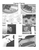

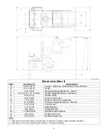
16
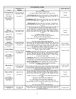
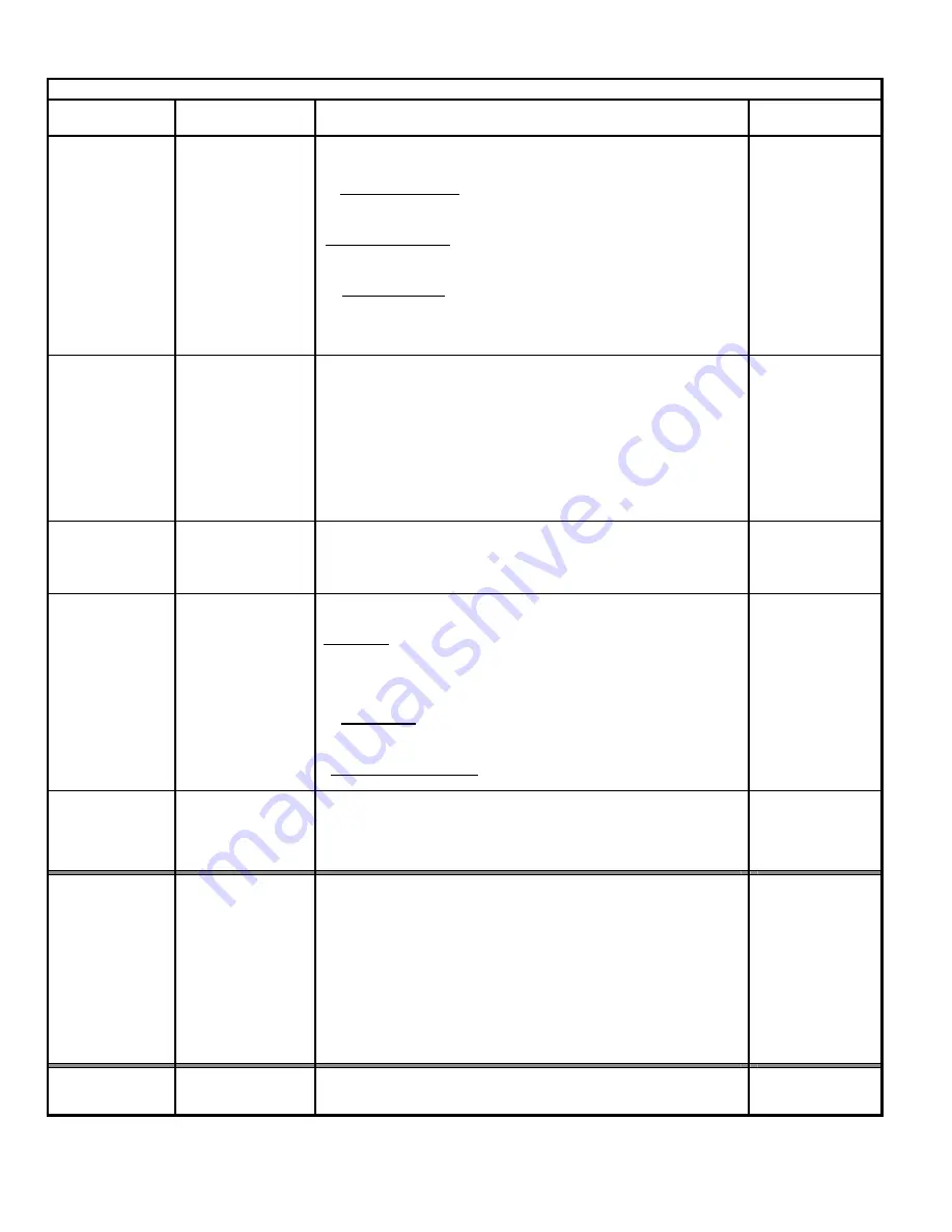
Tool Application Guide
Tool
Attachment To
Machine
Task
Surface Material
Grinding Stones
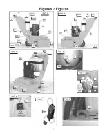
(See FIG. 14)
See Current
Product Catalog for
Part Numbers of
these Items.
Accessory Disk and
Wooden Wedges
(Section 4.1)
Light Grinding of Rough Areas
Available In Different Silicon Carbide “Grit” Sizes, such as:
TSC-10 Coarse Grit: Maximum material removal, General grinding &
removal of trowel marks, high spots, and rough sections of concrete. Life
4-10 hours.
TCS-24 Medium Grit: Lower material removal rate, Finer finish grinding of
concrete, and rough grinding of Terrazzo and other stone type. Life 6 – 10
hours.
TCS-80 Fine Grit: Still lower material removal rates. For polishing of
concrete and medium grinding on Terrazzo and stone type floors. Life 8 –
20 hours.
(The larger the number, the finer the grain structure, and the smoother the
surface material finish, and the longer the grinding stone life)
Concrete
Terrazzo
Other Stone Types
Diamond
Segment Blocks
(See FIG. 15)
See Current
Product Catalog for
Part Numbers of
these Items.
Accessory Disk and
Wooden Wedges
(Section 4.2)
Remove High Spots, Trowel & Rain Marks, Paints, Sealers & Mastics,
Uneven Joints, Aggressive Grinding of Large Rough Areas, Removal of
epoxies, paints and many thin film coatings, or Final Preparation for new
coating.
Available In Different “Grit” Sizes:
GB-10 General Purpose, GB-20 Abrasive Materials
GB-30 Epoxy & Non-Abrasive Materials.
Removal Rates: Up to five (5) times the material removal rate of Coarse
Grinding Stones.
Life: Up to 15 times the life of Grinding Stones.
Concrete
Terrazzo
Other Stone Types
Tungsten
Carbide Blocks
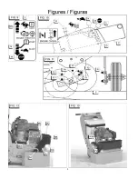
(FIG. 16, FIG. 17,
FIG. 18)
Accessory Disk and
Wooden Wedges
(Section 4.3)
Removal of Thick Paint Coatings, Not Recommended for Thin (< 5 mil)
Films of Materials. Not Recommended for adhesive, rubber deposits and
mastics which have a tendency to extrude or smear rather than “shear”
loose from the floor surface – however water or a water / sand mixture can
be added on the surface to reduce this problem.
Concrete, Epoxy,
Coatings, & Mastics
Scarifier Wheels
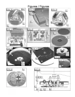
(FIG. 27, FIG. 28)
See Current
Product Catalog for
Part Numbers of
these Items.
Accessory Disk and
Wooden Wedges
(Section 4.4)
Remove Fiberglass, Ice, Oil-Dry, Foam-Fill Packing Material & Floor
Buildups. Lightly Texture Surface.
Star Wheel: Hardened Carbon Steel material. For removal of thin coatings
and encrusted accumulations of material. Cleaning concrete of asphalt
surfaces. Removing thick build-up of grease, paint, and some resins.
Light scarifying before application of coatings or sealer. Creates a swept,
or “broomed” type of finish.
Beam Wheel: Medium duty, for concrete and asphalt scarifying. De-
scaling steel decks. Removing thick material build-up of grease, paint, and
some resins. Twice the life, near the same cost as a star wheel.
Tungsten Carbide Wheel: Heavy Duty asphalt or concrete scarifying, or
de-scaling of steel decks. 10 times the life of a star wheel.
Concrete, and Tile
Wire Brushes
(FIG. 26)
Accessory Disk and
Wooden Wedges
(Section 4.5)
Light Scarifying & cleaning.
Notes: Should be rotated end for end in accessory disk every hour to avoid
the wire taking a set (flat wire will bend in one direction). External weight
added to machine will NOT normally increase production rates, but only
accelerate the wire brush wear rates.
Concrete, Asphalt,
Steel, and Tile
Diamond Disks
(FIG. 25)
See Current
Product Catalog for
Part Numbers of
these Items.
Adapter Plates
(Section 4.6)
Remove High Spots, Trowel & Rain Marks, Paints, Sealers & Mastics,
Uneven Joints, Aggressive Grinding of Large Rough Areas, Removal of
epoxies, paints and many thin film coatings, or Final Preparation for new
coating.
Available In Different “Grit” Sizes and 10 or 20 Diamond Segments (per
disk):
TDGH-10C for Cured Concrete (10 Segments)
TDGH-20C for Cured Concrete (20 Segments)
TDGH-20A for Asphalt or Abrasive Surfaces (20 Segments)
Removal Rates: Up to five (5) times the material removal rate of Grinding
Stones.
Life: Up to 15 times the life of Grinding Stones.
Concrete
Terrazzo
Other Stone Types
Scrubbing Pads
(FIG. 19)
Tool Holder Pad
(Section 4.7)
Remove mildew, rust, or discoloration from concrete, clean concrete forms,
strip scale and rust from steel plate surfaces, remove fins or marks on
underlayment materials.
Concrete, Steel
Summary of Contents for DT11H
Page 7: ...7...
Page 8: ...8...
Page 9: ...9...
Page 10: ...10...
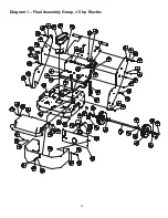
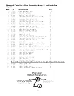
Page 28: ...28 Diagram 1 Final Assembly Group 1 5 hp Electric...
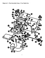
Page 30: ...30 Diagram 2 Final Assembly Group 11 hp Honda Gas...
Page 32: ...32 Diagram 3 Handle Group 1 5 hp Electric...
Page 36: ...36 Diagram 5 Motor Group 1 5 hp Electric...
Page 38: ...38 Diagram 6 Engine Group 11 hp Honda...
Page 40: ...40 Diagram 7 Gearbox Assembly All Models...
Page 42: ...42 Diagram 8 Water Tank Kit Optional P N 177855 Complete Kit...
Page 50: ...50 Diagram 15 Wiring Diagram 1 5hp Electric Model...


