

19
Electric Models:
The applicable national and local electrical
codes and enforcement bodies will be the
determining authority on the proper
connections and use of this machine. In all
cases it the operator/owner’s responsibility to
ensure that this equipment is in full
compliance with these codes.
All machine adjustments & maintenance shall
only be done after the machine’s power switch
has been put in the “OFF” position & the
power supply cord completely disconnected.
Make sure that the extension cord length is
properly sized for the motor used on this saw. See
the chart in Section 2 of this document.
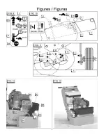
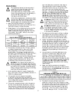
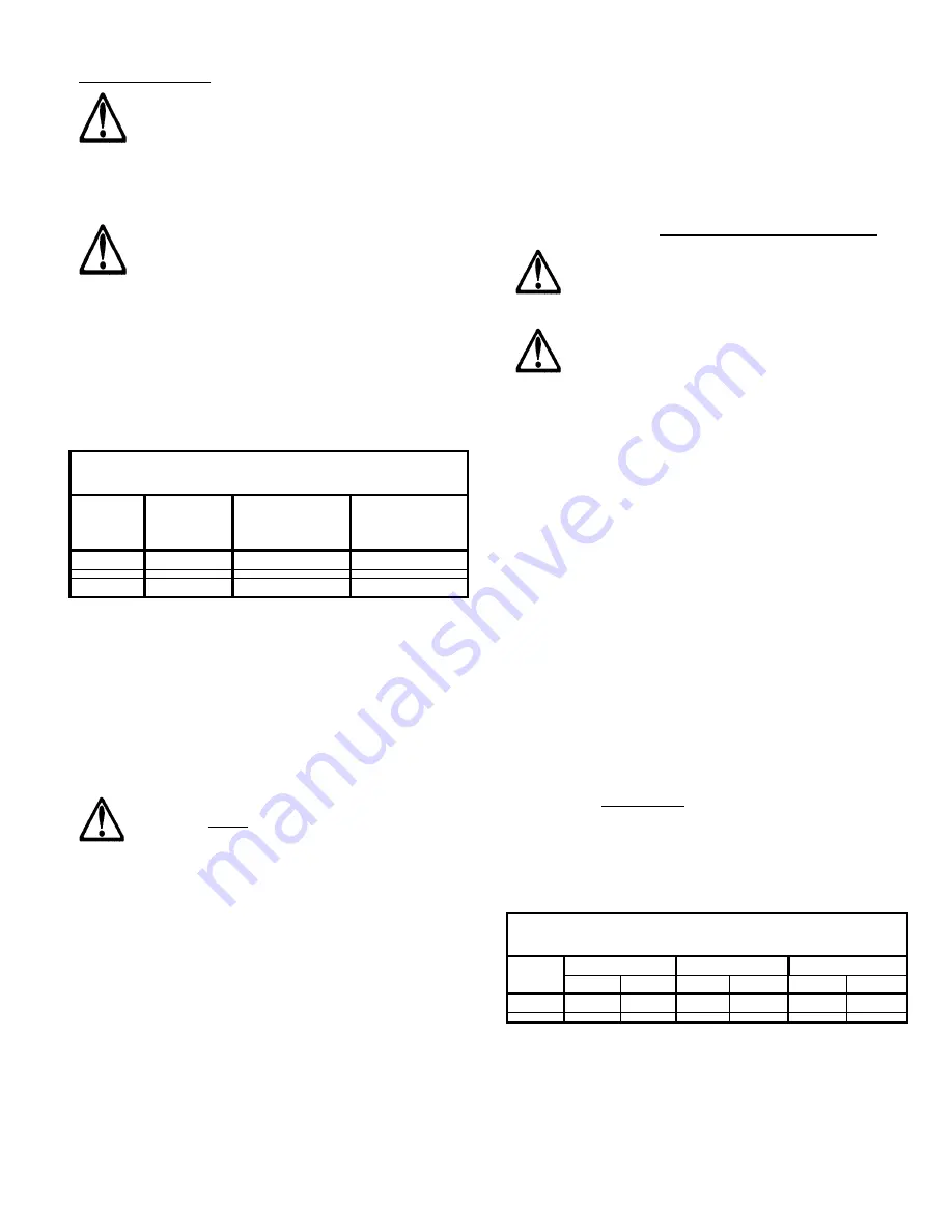
Single phase 1-1/2 hp motors are factory wired for
115 volt service and furnished with the correct
NEMA configuration Plug (LL) [See FIG. 1] on the
motor pigtail. See Table 1 below for the proper
matching connectors:
Table 1
Electric Motor Plugs & Connectors
Motor
Wired For
Voltage
Motor Pigtail
Plug
(NEMA No.)
Connector
Required
(NEMA No.)
1-1/2 HP
115 V
L5-20P
L5-20R
1-1/2 HP
230 V
L6-15P
L6-15R
For operator convenience, the 1-1/2 hp motor has
a Voltage Change Switch (J) [See FIG. 5] that
allows operation on a 115 VAC or a 230 VAC
power source. The voltage change switch (J) is
mounted on the terminal box of the motor and must
be set to either 115, or 230 Volt, to match the
voltage supply. Make sure that the Voltage Change
Lock Bolt (TT) is in position. It will prevent the
Voltage Change Switch [See FIG. 5] from being
accidentally moved into the wrong position.
WARNING: The Voltage Change Switch (J)
position is never to be changed while the motor
is running. Make sure that the Voltage Change
Lock Bolt (TT) is in position. It will prevent the
Voltage Change Switch from being accidentally
moved into the wrong position.
Local electrical codes may require changing the
plug on the motor to the proper NEMA connector to
match the voltage supply.
The operator must use plug and receptacle
connectors on all power cords (machine and
extension), designed and approved for the selected
motor voltage and equal to or greater than the
rated motor full load current.
The service receptacle, branch circuit conductors,
and overcurrent protection shall have an ampere
rating equal to or greater than the motor full load
current. According to the National Electrical Code
if the branch circuit has two or more receptacles,
each receptacle has a maximum load ampere
rating equal to 80% of the receptacle’s rating.
When this machine is set up to operate on 115
VAC, the motor has a full load rating of 19
amperes. This means that when operating this
machine on 115VAC, it can only be used on a
branch circuit with ONE 20-ampere rated
receptacle. If the circuit has two or more 20-
ampere receptacles, they each have load rating of
16 amperes and cannot be used by this machine.
WARNING: Always make sure the unit in
connected to a properly grounded electrical
outlet. Failure to comply with this warning
could result in serious bodily injury or death!
WARNING: DO NOT operate on low voltage!
Low voltage causes loss of power, motor
overheating, and possibly motor winding
burnout. Voltage should be checked at the
motor while it is operating.
The extension cord(s) used must have a voltage
rating greater than the selected voltage (115 or
230) and be sized for the rated motor full load
amps (as marked on motor specification plate).
Good motor performance depends on proper
voltage. Extension cords that are too long and / or
too small reduce the voltage to a motor under load.
Operating below this minimum voltage will cause
an increase in motor current resulting in slow
startup, and overheating in the motor and controls.
Sustained operation under these conditions will
result in permanent damage to the motor and
controls.
Long extension cords will probably have to be
oversized to minimize the voltage drop to the
machine. The size of the extension cord is
dependent on the total conductor length (all
extension cords) & the quality of the power source.
The power cord size shall be capable of supplying
a minimum of 90% of the motor nameplate
voltage at the motor, when the motor is running
rated full load.
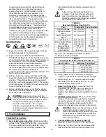
Make sure that the extension cord length is
properly sized for the motor used on this machine.
Use extension cords NO SMALLER than the sizes
indicated in Table 2 below:
Table 2
EXTENSION CORD SIZE (Minimum)
MOTOR
50 ft Long
75 ft Long
100 ft Long
HP
120 V
230 V
120
V
230 V
120 V
230 V
1-1/2
# 12
# 14
# 10
# 14
# 8
# 14
The branch circuit must have overcurrent
protection in the form of a circuit breaker or fuses.
The purpose of the overcurrent protection is to limit
the current in the branch circuit conductors and
connections to an amount equal to or less than
their ratings. This is to prevent overheating that
can lead to damage or a fire. The overcurrent
Summary of Contents for DT11H
Page 7: ...7...
Page 8: ...8...
Page 9: ...9...
Page 10: ...10...
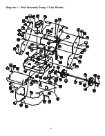
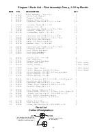
Page 28: ...28 Diagram 1 Final Assembly Group 1 5 hp Electric...
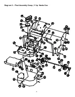
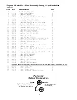
Page 30: ...30 Diagram 2 Final Assembly Group 11 hp Honda Gas...
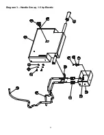
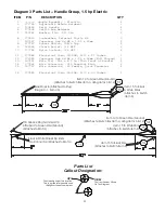
Page 32: ...32 Diagram 3 Handle Group 1 5 hp Electric...
Page 36: ...36 Diagram 5 Motor Group 1 5 hp Electric...
Page 38: ...38 Diagram 6 Engine Group 11 hp Honda...
Page 40: ...40 Diagram 7 Gearbox Assembly All Models...
Page 42: ...42 Diagram 8 Water Tank Kit Optional P N 177855 Complete Kit...
Page 50: ...50 Diagram 15 Wiring Diagram 1 5hp Electric Model...