


22
Scarifier Wheels to break and be thrown against
the inside of the machine frame.
4.5
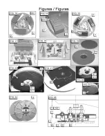
Wire Brushes [See FIG. 26]
For Light Scarifying and cleaning. Flat wires are
available in many sizes and configurations. They
should be rotated end-for-end in the Accessory Disk [P]
every hour to avoid the wire taking a “set” (wire will
bend in one direction). External weight added to
machine will NOT normally increase production rates,
but only accelerate the wire brush wear rates
.
4.6
Multi-Segmented Diamond Disks [Q]
[See FIG. 24 & FIG. 25]
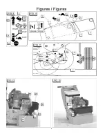
a) Temporary removal of the Front Shield (A) may be
required to complete this installation.
b) Attach
the
Multi-Segmented Diamond Disks (Q) to
the Adapter Plate (R) using the four (4) Flat Head
Screws (S1) and Thin Locknuts (S2) provided in
the Adapter Plate Kit (Kit Part Number 177861).
Tighten the Screws (S1) securely. Repeat this
procedure for the other Adapter Plate (R).
c) Attach
the
Diamond Disk / Adapter Plate Assembly
to the machine using the three (3) Capscrews (T1),
Lockwashers (T2), and Washers (T3) provided in
the Adapter Plate Kit. Tighten the Capscrews (T1)
securely. Repeat this procedure for the other
assembly.
d) Gently lower the front of the machine until the tools
touch the ground.
e) Pivot the axle so that it is in the Operation Position
[F] [See FIG. 11].
f) Lower
the
Front Shield [A] from its upper position.
Loosen the three (3) capscrews and lower the
shield so that it is only 3/8-1/2” (10-12 mm) from
the ground.
Notes: If machine starts to vibrate and shake try
removing external weight from the machine. If the
vibration continues, move the axle into the “E2” position
[See FIG. 11]. This position is normally a “transport”
position, but for the diamond disks it removes most of
the weight from the front of the machine and allows the
disks to glide over the surface rather than dig into the
surface.
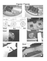
4.7
Tool Holding Pad (HH) Installation
[See FIG. 19, FIG. 20, FIG. 21, FIG. 22, FIG. 23]
This machine will allow the use of Scrubbing Pads [JJ]
that are available from another manufacture.
a) Position the triangular area of the Tool Holding
Pad [HH] [See FIG. 21] so that it mates with
the triangular area on the Accessory Disk [P].
b) Use the 1/2-20UNF x 1-1/4” Long Capscrew
[SS1] and Lockwasher [SS2] to attach the Tool
Holding Pad to the Accessory Disk. Tighten
the capscrew securely, using the ¾” (19 mm)
End of the Wrench [V] [Shown in FIG.8].
c) Repeat this procedure on the other Accessory
Disk [P].
d) Install the Scrubbing Pads [JJ], two (2) per
machine. Gently press the tool onto the hook
and loop fastening system until it is secure.
e) Gently lower the front of the machine until the
tools touch the ground.
f) Pivot the axle so that it is in the Operation
Position [F] [See FIG. 11].
g) Lower
the
Front Shield [A] from its upper
position. Loosen the three (3) capscrews [See
FIG. 2 & FIG. 3] and lower the shield so that it
is only 3/8-1/2” (10-12 mm) from the ground,
then re-tighten the three (3) capscrews.
5. Operating Instructions
All Models:
Configure the unit with the proper tool for the job.
See Section 4 of this document for tool installation.
Start / Stop of Electric Models:
WARNING: Make sure the Voltage Change
Switch (J) [See FIG. 5], is set to either 115, or
230 Volt, to match the voltage supply. The
Voltage Change Switch (J) position is never to
be changed while the motor is running.
Make sure that the Voltage Change Lock Bolt
(TT) is in position. It will prevent the Voltage
Change Switch from being accidentally moved
into the wrong position.
Local electrical codes may require changing
the Plug (LL) [See FIG. 1] on the motor to the
proper NEMA connector to match the voltage
supply.
WARNING: Always make sure the unit is
connected to a properly grounded electrical
outlet. Failure to comply with this warning
could result in serious bodily injury or death!
1) Before starting the electric motor (if set for 115 Volt
Operation) push down on the handles just enough
to release pressure from the grinding disks. Start
the electric motor by turning the Power Switch [H]
(See FIG. 6) to the ON position.
WARNING: DO NOT push down on the
handles enough to lift the grinding disks from
the ground.
2) Once the motor has reached full speed, reduce the
downward pressure applied to the handles and let
the weight of the machine rest on the ground.
3) Hold the handles firmly and gently guide the
machine over the work area.
Summary of Contents for DT11H
Page 7: ...7...
Page 8: ...8...
Page 9: ...9...
Page 10: ...10...
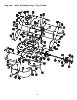
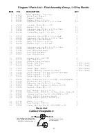
Page 28: ...28 Diagram 1 Final Assembly Group 1 5 hp Electric...
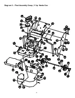
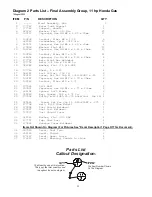
Page 30: ...30 Diagram 2 Final Assembly Group 11 hp Honda Gas...
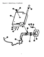
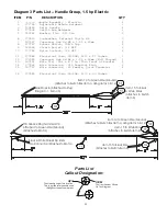
Page 32: ...32 Diagram 3 Handle Group 1 5 hp Electric...
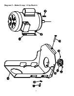
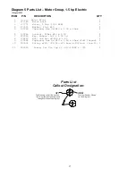
Page 36: ...36 Diagram 5 Motor Group 1 5 hp Electric...
Page 38: ...38 Diagram 6 Engine Group 11 hp Honda...
Page 40: ...40 Diagram 7 Gearbox Assembly All Models...
Page 42: ...42 Diagram 8 Water Tank Kit Optional P N 177855 Complete Kit...
Page 50: ...50 Diagram 15 Wiring Diagram 1 5hp Electric Model...