

24
Every 50 Hours:
1) All
Models:
a) Lubrication Points:
Lubricate every 50 hours using only a
Premium Lithium 12 based grease
conforming to NLG1 GRADE #2
consistency.
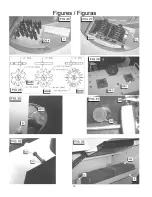
1) Spindle
Bearings: Six places total, three
Bearings [RR 1] on top of the gearbox
[FIG. 29] and three below the gearbox (Not
Shown).
2) Rear
Wheels:
Two places [FIG. 30].
2) Gasoline Model:
Change Engine Oil: Change engine
oil after every 50 hours of operation.
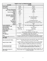
Engine Oil Type
Under normal operating conditions use SAE 10W30
API service classification SF or SG. See engine
operation manual for other recommended oil types.
Engine Oil Capacity (Honda GXV340)
1.16 U.S. Quarts
1.1 Liters
a) Engine Oil Change Procedure:
1. Drain the oil while the engine is still warm to
assure rapid and complete oil drain. Pivot the
Rear Axle To The Operation Position [F].
Place a bucket under the Oil Drain Hose [WW],
[FIG. 12, FIG. 13] to catch the used oil.
Remove the oil drain plug on the end of the Oil
Drain Hose [WW] and wait for all of the used oil
to be drained for the engine.
2. Re-install and securely tighten the plug in the
end of the Oil Drain Hose [WW].
3. Re-fill engine with the recommended oil type.
See the engine operation manual for the oil fill
location and proper oil level. Note that the
required oil capacity will be slightly larger
because of the volume of oil contained in the
Oil Drain Hose [WW].
4. Check the oil level. If the proper oil level is
indicated, re-install the oil fill cap.
5. Dispose of the used oil in a proper container
and in a manner that is compatible with the
environment.
When Required:
1) All
Models:
a) Lubrication:
Gearbox Grease Port [RR 3] [See FIG.
29]: Used to lubricate the transmission
gears, if required. These gears are factory
lubricated with 24 ounces (.68 kg) of
Lubriplate (Brand) 630-2 or equal, and
should not require any lubrication until
service work to the gears is required (at
500 – 1000 hours). Lubricate as required
with Lubriplate (Brand) 630-2 or equal. To
inspect the inside of the gearbox, remove
the two Capscrews that attach the Gearbox
Grease Port Cover [RR 3] and remove the
cover. A 1.00” (25 mm) hole in the
gearbox allows visual inspection of the
condition and quantity of the grease and
the gears.
Note: Early models have one removable
Capscrew that exposes a .50” (12 mm)
diameter inspection hole.
b) Replace Accessory Disk Isolators: Each of
the Accessory Disks [P] have six (6) rubber
isolators (See Parts List – Gearbox
Assembly) that constantly flex and move
as the machine operates. Over time the
isolators can deteriorate and wear out.
Check to see if they are damaged or
deteriorated, if so, replace immediately. All
twelve (12) isolators should be replaced as
a set.
c) V-Belt Inspection: Check to see that the V-
belts are not frayed or worn. If they are,
replace immediately.
8. V-Belt Tension
All Models:
Check V-Belt tension when unit is new and never set
belt tension beyond this point.
The machine is equipped with high tension V-Belts.
The belts are properly tensioned at the factory, but after
a few hours of operation they will stretch and become
loose.
a) Tensioning Blade Shaft V-Belts:
1) Loosen the four (4) Motor Base Capscrews
[ZZ] [FIG. 3] that attach the motor or
engine platform to the frame.
2) Loosen the Jam Nut [YY] [FIG. 32] until it is
not preventing the Belt Tensioning
Drawbolt [UU] from rotating.
3) Tighten the Belt Tensioning Drawbolt [UU]
[FIG. 32] until the V-belts are tightened to
the original factory tension.
4) Tighten the Jam Nut [YY] against the Motor
/ Engine Platform until the Belt Tensioning
Drawbolt [UU] is locked in position.
5) Re-tighten the four Capscrews [ZZ] that
attach the motor / engine platform [FIG. 3].
9. Important Advise
When storing for an extended period of time, use a
wire brush to remove hard, caked sludge. Clean
Summary of Contents for DT11H
Page 7: ...7...
Page 8: ...8...
Page 9: ...9...
Page 10: ...10...
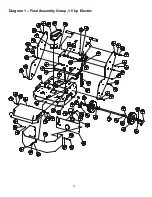
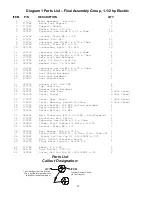
Page 28: ...28 Diagram 1 Final Assembly Group 1 5 hp Electric...
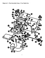
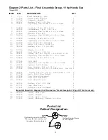
Page 30: ...30 Diagram 2 Final Assembly Group 11 hp Honda Gas...
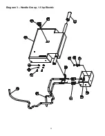
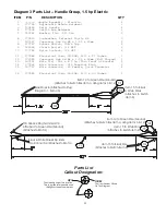
Page 32: ...32 Diagram 3 Handle Group 1 5 hp Electric...
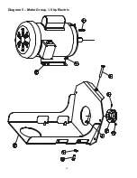
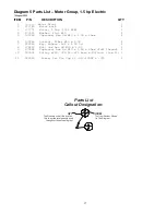
Page 36: ...36 Diagram 5 Motor Group 1 5 hp Electric...
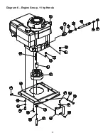
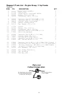
Page 38: ...38 Diagram 6 Engine Group 11 hp Honda...
Page 40: ...40 Diagram 7 Gearbox Assembly All Models...
Page 42: ...42 Diagram 8 Water Tank Kit Optional P N 177855 Complete Kit...
Page 50: ...50 Diagram 15 Wiring Diagram 1 5hp Electric Model...


