background image

20

TARGET FEED MASTER RF

TARGET FEED MASTER RF    rev.09

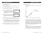
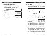
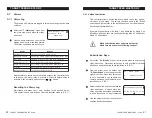
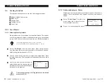
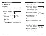
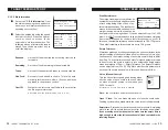
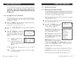
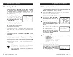
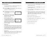
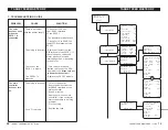
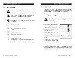
5.2   Starting a New Flock

Starting a new flock allows clearing all history menus associated

with the previous flock. The following steps show how to enter the

initial age and number of birds and how to enable the flock. Make

sure the feed distribution is enabled in the selected house before

starting the new flock (s. 5.5.3).

1- Select the 

"5.Start Flock" 

menu of

the desired house then press the right-

arrow key. The initial age is displayed.

Use the adjustment buttons to set it

to the desired value.

2- Press the down-arrow key. The initial

number of males flashes on the dis-

play. Use the adjustment buttons to

set the initial number of males.

3- Press the down-arrow key. The initial number of females flashes

on the display. Use the adjustment buttons to set the number of

female.

4- Press the down-arrow key.  The message 

"Start Flock?"

 flashes

on the display.

5- Press "+" to start the new flock. The posted answer "

Yes

" is

displayed for a 20 second delay then the displays returns to "

No

".

The new flock is now created. The previous history has been cleared.

If 2 houses are used, proceed the same way to start a new flock in

the other house.

All  histories are cleared when a new flock starts,

except for the alarm log and bin histories.

It is recommended to check the scale's accuracy

between each flock.

4.5  House  1  Start

Start Age:          1

Males  Entered:        20

Fem.  Entered:        200

Start Flock ?     No

53

TARGET FEED MASTER RF

TARGET FEED MASTER RF    rev.09

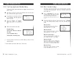
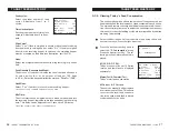
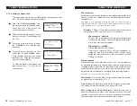
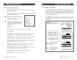
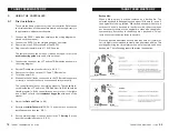
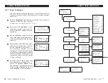
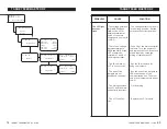
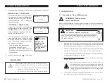
5.8.5.2 Assigning Relays to the Outputs

The relay assignment tells the controller which relay of which TRB

relay box is used for each controller's output.

Select "

9. Installation

" from the main menu using the up and down-

arrow keys. Press the right-arrow key.

Accessible from the installer mode only (s. 5.8.1).

Select the 

"4. Relay Assignment"

menu then press the right-arrow key.

Select the proper type of output from

the menu then press the right-arrow

key. The following parameters are dis-

played:

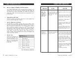
Mod: 

 This is the TRB box's ID number

(as defined in section 5.8.5.1).

Relay:

  This refers to the relay num-

ber. Relays are displayed in relation

with the chosen module.

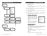
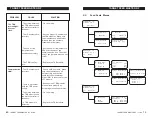
Select the proper TRB box and the relay for each activated output:

-  bin auger(s);

-  output auger(s);

-  feed drop(s)*;

-  clock output(s) (up to 8 relays can

   be assigned per clock output);

-  mixer.

* Note that the last feed drop of an out-

put auger does not necessarily need to

be connected to a relay. It can remain

permanently opened. In this case, you

must set the status of the last drop's

relay module to "None".

9.4.2  Auger  Relays

Output  Auger  1

Mod:   2  Rly       2

9.4    Relay  Assign.

1.      Bin  Augers

2.      Output  Augers

3.      Drop  Relays

4.      Time  Clock  Rlys

5.      Mixing  Relay

9.4.3  Drops  Relays

Drop  10

Mod:  None  Rly       x

Summary of Contents for FeedMaster-RF

Page 1: ...REV 03 M 890 00002 rev 09 Feed Scale TARGET FeedMaster RF User s Manual ...

Page 2: ...ation Settings 49 Technical specifications 66 R Relay assignment 51 52 Relay box ID number 52 Relay selection 53 Technical specifications 66 S Safety backup see Memory card Scale Calibration 56 Current weighing 22 Manual operation 49 Max Batch 48 Settings 48 Status 22 Valve activation 46 Weight s measurement units 46 Schedule see Feed cycles Serial number 2 Shortcut keys 11 12 Stick see Memory car...

Page 3: ...ion see Feed cycles Ingredient blends see Blends Mixing ingredients 46 Installation Controller s main settings 45 Installer password 44 K Keys 11 Shortcut keys 12 M Manual mode 57 Memory card 67 Mixer Activation 46 Activation Settings 46 Relay assignment 53 Mortalities 21 Mounting instructions 9 3 TARGET FEED MASTER RF rev 09 1 INTRODUCTION 5 1 1 Precautions Care Maintenance 5 1 2 List of Symbols ...

Page 4: ... 23 Backup bin 55 Bin augers relay assign ment 53 Remaining feed other bin info 24 Settings 54 Birds Bird age 22 Males females Feed drop selection 50 Number 21 Mortality 21 28 Number Posting initial of bird 20 Posting mortalities 21 Remaining number 21 Starting a new flock 20 Blends Activation 45 Blend curves Principle of operation 33 Settings 34 Blends substitution Activation 47 Operation Setting...

Page 5: ...EED MASTER RF TARGET FEED MASTER RF rev 09 1 INTRODUCTION 1 1 Precautions Care Maintenance WARNING Read and save these instructions Safety may be jeopardized if the equipment is used in a manner not specified by the manufacturer Carefully read and keep the following instructions for future reference Although fuses at the input and outputs of the controller protect its circuits in case of an overlo...

Page 6: ... your controller s configuration The card is also useful to transfer the configuration of one controller to another controller of the same type The switch at the bottom of the card is used to lock or to unlock the card locked unlocked Turn off power each time you open the controller s enclosure This prevents accidental exposure to areas of high voltage TO TRANSFER A CONFIGURATION 1 Turn off power ...

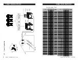
Page 7: ...termittent duty 10sec ON 30 sec OFF Housing IP54 plastic casing Operating temperature 0 to 40 C Storage temperature 15 to 50 C Ambient relative humidity max 95 Type TRB 8 Main supply fuse F2 1A fast blow Mains supply frequency 115 230V 10 20 20VA 50 60Hz Relay Output 1 8 10A Res 1 2HP 250VAC Housing IP54 plastic casing Operating temperature 0 to 40 C Storage temperature 15 to 50 C Ambient relative...

Page 8: ..._____ TIME CLOCK 7 2 _____ TIME CLOCK 1 8 _____ TIME CLOCK 7 3 _____ TIME CLOCK 2 1 _____ TIME CLOCK 7 4 _____ TIME CLOCK 2 2 _____ TIME CLOCK 7 5 _____ TIME CLOCK 2 3 _____ TIME CLOCK 7 6 _____ TIME CLOCK 2 4 _____ TIME CLOCK 7 7 _____ TIME CLOCK 2 5 _____ TIME CLOCK 7 8 _____ TIME CLOCK 2 6 _____ TIME CLOCK 8 1 _____ TIME CLOCK 2 7 _____ TIME CLOCK 8 2 _____ TIME CLOCK 2 8 _____ TIME CLOCK 8 3 _...

Page 9: ... water from enter ing the controller Insert the screws in the mounting holes and tighten Fasten the four black caps provided with the controller onto the four mounting holes The enclosure must be mounted in a location that will allow the cover to be completely opened right up against the wall 3 2 Connections 3 2 1 Controller s Main Wiring Refer to the wiring diagram enclosed with this user s manua...

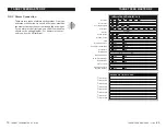
Page 10: ...RGET FEED MASTER RF TARGET FEED MASTER RF rev 09 of bins of houses of output augers of blends drops feed cycles of time clocks Use Mixer Mixing time Mix each batch Units Scale with valve Feed qty consumption Dump Separately Substitution Time of reset Shutoff augers on INSTALLATION SETTINGS SEC 5 8 2 2 1 3 NO YES LBS KG 4 2 6 1 5 3 4 2 1 1 to 20 2 1 2 6 1 5 3 4 8 7 Min Time clock 1 Time clock 2 Tim...

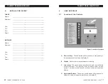
Page 11: ...___________________________________________ City ______________________________________________ Tel ______________________________________________ Fax ______________________________________________ Email ______________________________________________ 11 TARGET FEED MASTER RF TARGET FEED MASTER RF rev 09 4 USER INTERFACE 4 1 Location of the Controls A B C D Figure Controller s Faceplate A Shortcut ...

Page 12: ...e user to quickly step to the special preset functions on display The table beside shows the destination of these keys Table Shortcut Key Destination Short cut Keys Destination 1 Bin Information 2 House 1 Information 3 House 1 of Animals 4 House 1 Start Flock 5 House 2 Information 6 House 2 of Animals 61 TARGET FEED MASTER RF TARGET FEED MASTER RF rev 09 PROBLEM CAUSE SOLUTION Max Run Time Alarm o...

Page 13: ... There is a problem with the TRB power supply The wiring between the TRB modules and the main controller is incorrect Fix the wiring Make sure all TRB modules are powered properly by activating manually each relay A TRB module is defective Replace the TRB module 13 TARGET FEED MASTER RF TARGET FEED MASTER RF rev 09 4 3 Feed Scale Menus 1 Date Time Menu 1 Date Time 1 Date Time Date 200X 01 01 Time ...

Page 14: ... and 4 of the main controller The voltage between terminals PWR and GND of the LCT or between terminals 1 and 4 of the main controller is too low 5 11VDC The LCT light does not flash The voltage selector switch is in the wrong position Set the switch to the correct position Fuse F2 of the main controller is blown Turn the power off and replace the fuse If the fuse blows regularly check the wiring ...

Page 15: ...terminals of the main controller Wait 5 minutes Apply power to the main controller If the controller starts then there is a wiring problem Fix the wiring 15 TARGET FEED MASTER RF TARGET FEED MASTER RF rev 09 FeedWeigher for Breeders V X X 4 House 1 4 House 1 2 Consumption 4 2 House1 Cons M 100 250g Males Tot 10 kg F 100 700g Fem Tot 35 kg 4 House 1 3 Feed Schedule 4 3 House1 Feed Schedule 1 Feedin...

Page 16: ...e or abort a running feed cycle or to start a cycle Select the desired house from the main menu using the arrow keys Press the right arrow key Select 3 Feed Schedule using the down arrow key Press the right arrow key Press the down arrow key in order to select the 4 Manual Mode menu then press the right arrow key To Pause or Abort a Cycle Pause Select Yes to pause the ongoing cycle This function i...

Page 17: ...cale 1 Calib weight 10 00 Push for next step Scale is Empty Scale 1 Calib weight 10 00 Push for next step Scale is Laden Scale 1 Calib weight 10 00 Push for next step Scale is Saved 17 TARGET FEED MASTER RF TARGET FEED MASTER RF rev 09 FeedWeigher for Breeders V X X 9 Installation 9 Installation 1 Settings 9 Installation 2 Scale Settings Actual Weight 0 00 Max Batch 20kg Prox Switch Yes Stability ...

Page 18: ...inside the LCT and in the TRB module with ID 2 should be flashing regularly If the controller does now work or if the lights do not flash refer to the troubleshooting guide at the end of the manual 3 Adjust the Date and Time s 5 4 4 Enter the Installer Password 03 05 14 by default to access the installation menu see sec 5 8 1 5 Set the main settings of the controller in the 1 Settings menu from th...

Page 19: ... continues running even though the re order point alarm is active Use the adjustment buttons to set the re order point to the desired value Alarm if empty Select Yes if you want an alarm to be set off when the bin is empty When this type of alarm is active the system stops oper ating except if a backup bin is selected see below 9 Installation 5 Bin Settings 9 5 1 Bin 1 Settings Max fill time 15 Re...

Page 20: ... log and bin histories It is recommended to check the scale s accuracy between each flock 4 5 House 1 Start Start Age 1 Males Entered 20 Fem Entered 200 Start Flock No 53 TARGET FEED MASTER RF TARGET FEED MASTER RF rev 09 5 8 5 2 Assigning Relays to the Outputs The relay assignment tells the controller which relay of which TRB relay box is used for each controller s output Select 9 Installation fr...

Page 21: ... relay 17 32 21 TARGET FEED MASTER RF TARGET FEED MASTER RF rev 09 5 3 Monitoring Functions 5 3 1 Monitoring the Number of Birds It is possible to keep a tally of the number of birds in each house To do so the user must post up every change that occurs in the number of birds mortalities new animal entries Refer to sec tion 5 2 to post up the initial number of birds Hint The following menu can quic...

Page 22: ...tput Auger Shows which output auger is currently active This value does not appear if no feed cycle is active Current Drop Shows which drop is currently active This value does not appear if no feed cycle is activated Actual Weight Current amount of feed in the scale Scale Status Fill Weigh Dump Close 4 1 House 1 Info Age 10 Feed Today Yes Current Cycle 2 Total Weight 20 Delivered 3 Bin Auger 2 Cur...

Page 23: ...mped in the receiving hopper Animal Type Select whether the drop serves males or females 9 Installation 3 Drop Settings 9 3 Drop Settings 1 Drop 1 2 Drop 2 9 3 1 Drop 1 Output Auger 1 House 2 RunTime 1 00 m s Animal Type Fem 23 TARGET FEED MASTER RF TARGET FEED MASTER RF rev 09 5 3 3 Bin Management The bin information menu allows monitoring the amount of feed that remains in the bins 5 3 3 1 Addin...

Page 24: ...ng hopper It can be adjusted from 1 to 1000 grams It is NOT recommended to change this value unless weighing errors that are caused by wind or other vibration source occur In this case the stability tolerance can be increased to 150 175 grams The default stability tolerance value is set to 100 grams Empty Tolerance Vibrations produced by the output auger can cause variations in the weight reading ...

Page 25: ...wing If it is enabled the controller automatically sets off an alarm when feed is detected by this sen sor this means the receiving hopper is full The bin auger is also stopped when this type of alarm occurs 9 Installation 2 Scale Settings Actual Weight 0 00 Max Batch 20kg Prox Switch Yes Stability tol 100 Empty tolerance 0 Valve Auto Empty time 1 00 25 TARGET FEED MASTER RF TARGET FEED MASTER RF ...

Page 26: ...sed This weighing method is automati cally performed if your scale does not have a valve Example 100 kg of feed must be delivered and the blend is composed of 30 from bin 1 and 70 from bin 2 Mix each batch disabled 30 kg of bin 1 is weighed in the scale and is then dumped in the receiving hopper The second ingredient 70kg of bin 2 then starts being weighed Mix each batch enabled with a Max Batch S...

Page 27: ...es This menu appears if the mixer is enabled above Feed cycles 2 time clocks 8 With Valve Yes Units kg Feed qty Total Use Mixer No Mix Time 0 30 m s 27 TARGET FEED MASTER RF TARGET FEED MASTER RF rev 09 5 3 4 Viewing Today s Feed Consumption The consumption menu shows the amount of feed consumed per hundred birds and the total amount of feed consumed in each house The male and female consumption i...

Page 28: ...ER RF rev 09 5 8 2 Main Controller Settings The following section describes how to customize the controller for your particular application Normally this setup needs to be done only once Select 9 Installation from the main menu using the up and down arrow keys Press the right arrow key Accessible from the installer mode only s 5 8 1 Press the right arrow key once again to select the 1 Settings men...

Page 29: ... 09 5 4 Setting the Time and Date Select the 1 Date Time menu from the main menu then press the right arrow key three times The year begins to flash Use the adjustment buttons to set the year Note that the date format may vary depending on the controller configuration Press the right arrow key The month flashes on the display Use the adjust ment buttons to set the month Press the right arrow key T...

Page 30: ... is only available if blends have been en abled during the installation s 5 8 2 Use the up and down arrow keys to select the desired blend Press the right arrow key The proportion of feed taken from each bin is displayed Use the up and down arrow keys to select the desired bin then use the ad justment buttons to set the desired pro portion of this ingredient The total percentage of all ingredients...

Page 31: ... T n O r e w o P n o d e n r u t n e e b s a h r e l l o r t n o c e h t n e h w s w o h S 1 c s h c t i w s x o r p x a M d e e f s t c e t e d h c t i w s y t i m i x o r p e h T Feed Weigher for Breeders VX X 7 Alarm Log 31 TARGET FEED MASTER RF TARGET FEED MASTER RF rev 09 5 5 1 2 Blend Substitution The controller allows switching from a blend to another on spe cific days of the week To use th...

Page 32: ...ces such as lights or feed loops Each output can per form up to 10 cycles per day Use the arrow keys to select the 6 Time Clocks from the main menu Accessible if time clocks are enabled s 5 8 2 Use the arrow keys to select the de sired time clock Select the desired operating mode Alw the clock output runs everyday Feed 1 the clock output only runs during feeding days of house 1 Feed 2 the clock ou...

Page 33: ...ess the up arrow key to select Use curve menu Select Yes to enable the curve 2b Feed Curves 1 Males 2 Females 2b 1 M Feed Curve Use curve No 1 Day 1 Feed 20 2 2 Day 15 Feed 25 5 33 TARGET FEED MASTER RF TARGET FEED MASTER RF rev 09 5 5 2 Blend Curves The user can define a blend curve to adjust the blends automatically over a period of up to 450 days Male and female blend curves are set separately ...

Page 34: ...rrow key to select Use curve menu Select Yes to enable the curve 4 7 House 1 Blend Curves 1 Males 2 Females 4 7 1 M Blend Curve Use curve No 1 Da 1 Blend 1 2 Da 25 Blend 2 39 TARGET FEED MASTER RF TARGET FEED MASTER RF rev 09 5 5 5 Feed Curves Feed curves are used to adjust the feed ration of males and fe males with time A curve is defined using up to ten points Each point specifies a day number a...

Page 35: ...lt the controller distributes feed every day It is also pos sible to specify an interval at which feeding days are skipped Use the arrow keys to select the de sired house from the main menu Use the arrow keys to select the 3 Feed Schedule menu Press the right arrow key once again to select 1 Feeding Days menu Set the frequency at which feeding days are skipped as follows Frequency This is the freq...

Page 36: ...GET FEED MASTER RF TARGET FEED MASTER RF rev 09 Feed Cycles Status This menu shows the status of feeding cycles Select ON to en able a cycle or OFF to disable it Start Time This is the time at which the selected cycle starts Use the adjust ment buttons to set the start time to the desired value Males Females 100 This is the amount of feed per hundred males or per hundred fe males that will be deli...

Page 37: ...GET FEED MASTER RF TARGET FEED MASTER RF rev 09 Feed Cycles Status This menu shows the status of feeding cycles Select ON to en able a cycle or OFF to disable it Start Time This is the time at which the selected cycle starts Use the adjust ment buttons to set the start time to the desired value Males Females 100 This is the amount of feed per hundred males or per hundred fe males that will be deli...

Page 38: ...lt the controller distributes feed every day It is also pos sible to specify an interval at which feeding days are skipped Use the arrow keys to select the de sired house from the main menu Use the arrow keys to select the 3 Feed Schedule menu Press the right arrow key once again to select 1 Feeding Days menu Set the frequency at which feeding days are skipped as follows Frequency This is the freq...

Page 39: ...rrow key to select Use curve menu Select Yes to enable the curve 4 7 House 1 Blend Curves 1 Males 2 Females 4 7 1 M Blend Curve Use curve No 1 Da 1 Blend 1 2 Da 25 Blend 2 39 TARGET FEED MASTER RF TARGET FEED MASTER RF rev 09 5 5 5 Feed Curves Feed curves are used to adjust the feed ration of males and fe males with time A curve is defined using up to ten points Each point specifies a day number a...

Page 40: ...ess the up arrow key to select Use curve menu Select Yes to enable the curve 2b Feed Curves 1 Males 2 Females 2b 1 M Feed Curve Use curve No 1 Day 1 Feed 20 2 2 Day 15 Feed 25 5 33 TARGET FEED MASTER RF TARGET FEED MASTER RF rev 09 5 5 2 Blend Curves The user can define a blend curve to adjust the blends automatically over a period of up to 450 days Male and female blend curves are set separately ...

Page 41: ...ces such as lights or feed loops Each output can per form up to 10 cycles per day Use the arrow keys to select the 6 Time Clocks from the main menu Accessible if time clocks are enabled s 5 8 2 Use the arrow keys to select the de sired time clock Select the desired operating mode Alw the clock output runs everyday Feed 1 the clock output only runs during feeding days of house 1 Feed 2 the clock ou...

Page 42: ... T n O r e w o P n o d e n r u t n e e b s a h r e l l o r t n o c e h t n e h w s w o h S 1 c s h c t i w s x o r p x a M d e e f s t c e t e d h c t i w s y t i m i x o r p e h T Feed Weigher for Breeders VX X 7 Alarm Log 31 TARGET FEED MASTER RF TARGET FEED MASTER RF rev 09 5 5 1 2 Blend Substitution The controller allows switching from a blend to another on spe cific days of the week To use th...

Page 43: ... is only available if blends have been en abled during the installation s 5 8 2 Use the up and down arrow keys to select the desired blend Press the right arrow key The proportion of feed taken from each bin is displayed Use the up and down arrow keys to select the desired bin then use the ad justment buttons to set the desired pro portion of this ingredient The total percentage of all ingredients...

Page 44: ... 09 5 4 Setting the Time and Date Select the 1 Date Time menu from the main menu then press the right arrow key three times The year begins to flash Use the adjustment buttons to set the year Note that the date format may vary depending on the controller configuration Press the right arrow key The month flashes on the display Use the adjust ment buttons to set the month Press the right arrow key T...

Page 45: ...ER RF rev 09 5 8 2 Main Controller Settings The following section describes how to customize the controller for your particular application Normally this setup needs to be done only once Select 9 Installation from the main menu using the up and down arrow keys Press the right arrow key Accessible from the installer mode only s 5 8 1 Press the right arrow key once again to select the 1 Settings men...

Page 46: ...es This menu appears if the mixer is enabled above Feed cycles 2 time clocks 8 With Valve Yes Units kg Feed qty Total Use Mixer No Mix Time 0 30 m s 27 TARGET FEED MASTER RF TARGET FEED MASTER RF rev 09 5 3 4 Viewing Today s Feed Consumption The consumption menu shows the amount of feed consumed per hundred birds and the total amount of feed consumed in each house The male and female consumption i...

Page 47: ...sed This weighing method is automati cally performed if your scale does not have a valve Example 100 kg of feed must be delivered and the blend is composed of 30 from bin 1 and 70 from bin 2 Mix each batch disabled 30 kg of bin 1 is weighed in the scale and is then dumped in the receiving hopper The second ingredient 70kg of bin 2 then starts being weighed Mix each batch enabled with a Max Batch S...

Page 48: ...wing If it is enabled the controller automatically sets off an alarm when feed is detected by this sen sor this means the receiving hopper is full The bin auger is also stopped when this type of alarm occurs 9 Installation 2 Scale Settings Actual Weight 0 00 Max Batch 20kg Prox Switch Yes Stability tol 100 Empty tolerance 0 Valve Auto Empty time 1 00 25 TARGET FEED MASTER RF TARGET FEED MASTER RF ...

Page 49: ...ng hopper It can be adjusted from 1 to 1000 grams It is NOT recommended to change this value unless weighing errors that are caused by wind or other vibration source occur In this case the stability tolerance can be increased to 150 175 grams The default stability tolerance value is set to 100 grams Empty Tolerance Vibrations produced by the output auger can cause variations in the weight reading ...

Page 50: ...mped in the receiving hopper Animal Type Select whether the drop serves males or females 9 Installation 3 Drop Settings 9 3 Drop Settings 1 Drop 1 2 Drop 2 9 3 1 Drop 1 Output Auger 1 House 2 RunTime 1 00 m s Animal Type Fem 23 TARGET FEED MASTER RF TARGET FEED MASTER RF rev 09 5 3 3 Bin Management The bin information menu allows monitoring the amount of feed that remains in the bins 5 3 3 1 Addin...

Page 51: ...tput Auger Shows which output auger is currently active This value does not appear if no feed cycle is active Current Drop Shows which drop is currently active This value does not appear if no feed cycle is activated Actual Weight Current amount of feed in the scale Scale Status Fill Weigh Dump Close 4 1 House 1 Info Age 10 Feed Today Yes Current Cycle 2 Total Weight 20 Delivered 3 Bin Auger 2 Cur...

Page 52: ... relay 17 32 21 TARGET FEED MASTER RF TARGET FEED MASTER RF rev 09 5 3 Monitoring Functions 5 3 1 Monitoring the Number of Birds It is possible to keep a tally of the number of birds in each house To do so the user must post up every change that occurs in the number of birds mortalities new animal entries Refer to sec tion 5 2 to post up the initial number of birds Hint The following menu can quic...

Page 53: ... log and bin histories It is recommended to check the scale s accuracy between each flock 4 5 House 1 Start Start Age 1 Males Entered 20 Fem Entered 200 Start Flock No 53 TARGET FEED MASTER RF TARGET FEED MASTER RF rev 09 5 8 5 2 Assigning Relays to the Outputs The relay assignment tells the controller which relay of which TRB relay box is used for each controller s output Select 9 Installation fr...

Page 54: ... continues running even though the re order point alarm is active Use the adjustment buttons to set the re order point to the desired value Alarm if empty Select Yes if you want an alarm to be set off when the bin is empty When this type of alarm is active the system stops oper ating except if a backup bin is selected see below 9 Installation 5 Bin Settings 9 5 1 Bin 1 Settings Max fill time 15 Re...

Page 55: ...inside the LCT and in the TRB module with ID 2 should be flashing regularly If the controller does now work or if the lights do not flash refer to the troubleshooting guide at the end of the manual 3 Adjust the Date and Time s 5 4 4 Enter the Installer Password 03 05 14 by default to access the installation menu see sec 5 8 1 5 Set the main settings of the controller in the 1 Settings menu from th...

Page 56: ...cale 1 Calib weight 10 00 Push for next step Scale is Empty Scale 1 Calib weight 10 00 Push for next step Scale is Laden Scale 1 Calib weight 10 00 Push for next step Scale is Saved 17 TARGET FEED MASTER RF TARGET FEED MASTER RF rev 09 FeedWeigher for Breeders V X X 9 Installation 9 Installation 1 Settings 9 Installation 2 Scale Settings Actual Weight 0 00 Max Batch 20kg Prox Switch Yes Stability ...

Page 57: ...e or abort a running feed cycle or to start a cycle Select the desired house from the main menu using the arrow keys Press the right arrow key Select 3 Feed Schedule using the down arrow key Press the right arrow key Press the down arrow key in order to select the 4 Manual Mode menu then press the right arrow key To Pause or Abort a Cycle Pause Select Yes to pause the ongoing cycle This function i...

Page 58: ...terminals of the main controller Wait 5 minutes Apply power to the main controller If the controller starts then there is a wiring problem Fix the wiring 15 TARGET FEED MASTER RF TARGET FEED MASTER RF rev 09 FeedWeigher for Breeders V X X 4 House 1 4 House 1 2 Consumption 4 2 House1 Cons M 100 250g Males Tot 10 kg F 100 700g Fem Tot 35 kg 4 House 1 3 Feed Schedule 4 3 House1 Feed Schedule 1 Feedin...

Page 59: ... and 4 of the main controller The voltage between terminals PWR and GND of the LCT or between terminals 1 and 4 of the main controller is too low 5 11VDC The LCT light does not flash The voltage selector switch is in the wrong position Set the switch to the correct position Fuse F2 of the main controller is blown Turn the power off and replace the fuse If the fuse blows regularly check the wiring ...

Page 60: ... There is a problem with the TRB power supply The wiring between the TRB modules and the main controller is incorrect Fix the wiring Make sure all TRB modules are powered properly by activating manually each relay A TRB module is defective Replace the TRB module 13 TARGET FEED MASTER RF TARGET FEED MASTER RF rev 09 4 3 Feed Scale Menus 1 Date Time Menu 1 Date Time 1 Date Time Date 200X 01 01 Time ...

Page 61: ...e user to quickly step to the special preset functions on display The table beside shows the destination of these keys Table Shortcut Key Destination Short cut Keys Destination 1 Bin Information 2 House 1 Information 3 House 1 of Animals 4 House 1 Start Flock 5 House 2 Information 6 House 2 of Animals 61 TARGET FEED MASTER RF TARGET FEED MASTER RF rev 09 PROBLEM CAUSE SOLUTION Max Run Time Alarm o...

Page 62: ...___________________________________________ City ______________________________________________ Tel ______________________________________________ Fax ______________________________________________ Email ______________________________________________ 11 TARGET FEED MASTER RF TARGET FEED MASTER RF rev 09 4 USER INTERFACE 4 1 Location of the Controls A B C D Figure Controller s Faceplate A Shortcut ...

Page 63: ...RGET FEED MASTER RF TARGET FEED MASTER RF rev 09 of bins of houses of output augers of blends drops feed cycles of time clocks Use Mixer Mixing time Mix each batch Units Scale with valve Feed qty consumption Dump Separately Substitution Time of reset Shutoff augers on INSTALLATION SETTINGS SEC 5 8 2 2 1 3 NO YES LBS KG 4 2 6 1 5 3 4 2 1 1 to 20 2 1 2 6 1 5 3 4 8 7 Min Time clock 1 Time clock 2 Tim...

Page 64: ... water from enter ing the controller Insert the screws in the mounting holes and tighten Fasten the four black caps provided with the controller onto the four mounting holes The enclosure must be mounted in a location that will allow the cover to be completely opened right up against the wall 3 2 Connections 3 2 1 Controller s Main Wiring Refer to the wiring diagram enclosed with this user s manua...

Page 65: ..._____ TIME CLOCK 7 2 _____ TIME CLOCK 1 8 _____ TIME CLOCK 7 3 _____ TIME CLOCK 2 1 _____ TIME CLOCK 7 4 _____ TIME CLOCK 2 2 _____ TIME CLOCK 7 5 _____ TIME CLOCK 2 3 _____ TIME CLOCK 7 6 _____ TIME CLOCK 2 4 _____ TIME CLOCK 7 7 _____ TIME CLOCK 2 5 _____ TIME CLOCK 7 8 _____ TIME CLOCK 2 6 _____ TIME CLOCK 8 1 _____ TIME CLOCK 2 7 _____ TIME CLOCK 8 2 _____ TIME CLOCK 2 8 _____ TIME CLOCK 8 3 _...

Page 66: ...termittent duty 10sec ON 30 sec OFF Housing IP54 plastic casing Operating temperature 0 to 40 C Storage temperature 15 to 50 C Ambient relative humidity max 95 Type TRB 8 Main supply fuse F2 1A fast blow Mains supply frequency 115 230V 10 20 20VA 50 60Hz Relay Output 1 8 10A Res 1 2HP 250VAC Housing IP54 plastic casing Operating temperature 0 to 40 C Storage temperature 15 to 50 C Ambient relative...

Page 67: ... your controller s configuration The card is also useful to transfer the configuration of one controller to another controller of the same type The switch at the bottom of the card is used to lock or to unlock the card locked unlocked Turn off power each time you open the controller s enclosure This prevents accidental exposure to areas of high voltage TO TRANSFER A CONFIGURATION 1 Turn off power ...

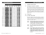
Page 68: ...EED MASTER RF TARGET FEED MASTER RF rev 09 1 INTRODUCTION 1 1 Precautions Care Maintenance WARNING Read and save these instructions Safety may be jeopardized if the equipment is used in a manner not specified by the manufacturer Carefully read and keep the following instructions for future reference Although fuses at the input and outputs of the controller protect its circuits in case of an overlo...

Page 69: ... 23 Backup bin 55 Bin augers relay assign ment 53 Remaining feed other bin info 24 Settings 54 Birds Bird age 22 Males females Feed drop selection 50 Number 21 Mortality 21 28 Number Posting initial of bird 20 Posting mortalities 21 Remaining number 21 Starting a new flock 20 Blends Activation 45 Blend curves Principle of operation 33 Settings 34 Blends substitution Activation 47 Operation Setting...

Page 70: ...ion see Feed cycles Ingredient blends see Blends Mixing ingredients 46 Installation Controller s main settings 45 Installer password 44 K Keys 11 Shortcut keys 12 M Manual mode 57 Memory card 67 Mixer Activation 46 Activation Settings 46 Relay assignment 53 Mortalities 21 Mounting instructions 9 3 TARGET FEED MASTER RF rev 09 1 INTRODUCTION 5 1 1 Precautions Care Maintenance 5 1 2 List of Symbols ...

Page 71: ...ation Settings 49 Technical specifications 66 R Relay assignment 51 52 Relay box ID number 52 Relay selection 53 Technical specifications 66 S Safety backup see Memory card Scale Calibration 56 Current weighing 22 Manual operation 49 Max Batch 48 Settings 48 Status 22 Valve activation 46 Weight s measurement units 46 Schedule see Feed cycles Serial number 2 Shortcut keys 11 12 Stick see Memory car...

Page 72: ...REV 03 M 890 00002 rev 09 Feed Scale TARGET FeedMaster RF User s Manual ...

Reviews: