17
SPECIAL OUTER FLANGE ASSY 1/2" (12.7mm)
WIDE CUT (P/N 167963)
•
A Special Outer Flange Assembly is available as a field
installed accessory. It enables the MC 18 to cut
7/16" - 1/2" (11-12.7mm) wide.
WARNING: This special outer flange assembly
is for use with blade width stacks of 7/16" -
1/2" (11mm-12.7mm) only! If blade width stacks
of less than 7/16" (11mm) are required, use the
standard outer flange assembly supplied with
the MC 18. The Special Outer Flange Assembly
can be identified by the COUNTERBORE on the
“Nut Side” of the flange. The Standard Outer
Flange Assembly has NO COUNTERBORE.
WATER TANK KIT
•
A 6 gallon (23 liter) Water Tank Kit is available as a
Field installed accessory. Use only for dry cutting!
The water tank is designed only to suppress airborne
concrete dust.
WARNING: DO NOT use conventional (wet)
diamond blades with the water tank as the
water source, because there is not sufficient
water flow available to properly cool the blades!
TIE DOWN BRACKET KIT (P/N 167189)
•
A Tie Down Bracket Kit is available as a field installed
accessory. The kit consists of two (2) tie down loops
that are installed at the front of the frame. They are to
be used only to SECURE the saw to a truck or trailer
during transport.
WARNING: DO NOT use the tie down
brackets as a device for lifting the saw!
Before performing any maintenance, ALWAYS
park the machine on a level surface with the
Engine OFF and the Engine Switch in the "OFF"
position.
After each use:
CLEAN the machine.
LUBRICATION:
LUBRICATE DAILY
Front Wheels and Blade Shaft Bearings
LUBRICATE EVERY 50 HOURS
Depth Control Adjustment Screw (Screw Feed Version Only)
NOTE: When cutting dry, lubricate blade shaft bearings 2
or 3 times daily, the grease provides an added protective
seal for the bearings. Use only a Premium Lithium 12
based Grease, conforming to NLG1 Grade #2 Consistency,
without Molybdenum Disulfide.
ENGINE OIL:
Check daily. Keep the oil clean and at the proper level.
10W30 MS, SD, SE or better is generally recommended.
Capacity levels indicated on page 10.
DO NOT OVER-
FILL!!
Change engine oil and oil filter every 50 HOURS of
operation. Refer to the engine manual for detailed informa-
tion.
CLEAN ENGINE AIR FILTER:
Clean the air filter 2 or 3 times daily when dry cutting. Refer
to the engine manual for detailed information.
ENGINE CARE:
Refer to the engine manual for detailed information.
A.
On Air Models:
A filter with a lubricator and a shut-off valve has been
provided on the saw. Lubrication of the air motor is
required. Lubrication is necessary for all internal
moving parts and rust prevention. The filter removes
excessive moisture in the air line that can cause rust
formation in the motor and might also cause ice to form
in the muffler due to expansion of air thru the motor.
The filter has a manual drain and must be drained as
frequently as necessary to keep the liquid level in the
bowl below the baffle. If the liquid level rises above the
baffle, liquid will be carried into the air motor.
B.
On Electric Models:
Check the extension wire size. Under-sized wires can
cause motor burn out. Use No. 8 wire for extension
cord lengths up to 100 ft. long
BLADE SHAFT V-BELTS:
This concrete saw is equipped with “3VX” premium V-belts.
These belts are properly tensioned at the factory. Severe
damage or breakage of the crankshaft can occur if the belts
are tensioned too tightly. Check the belt tension as set on
the new saw and NEVER set belts beyond the original tension.
Not enough tension will destroy the belts quickly, and the
belts should NEVER be allowed to slip. After one (1) hour of
use, retension the belts to make up for initial stretch. A
V-belt tension tester should be used to obtain accurate V-belt
tension settings. Check the setting in a SINGLE belt of a set
of V-belts. Apply the load at the center of the belt span.
Deflection should be 3/16" (5mm) with a 5 to 6 lb. (2.3 to 2.7
kg.) load.
Replace the belts in sets only.
10
Maintenance
11
Optional and Accessory (Field Installed)
Summary of Contents for MC18
Page 3: ...3 NOTE NOTA...
Page 8: ...8 NOTE NOTA...
Page 19: ...19 NOTE NOTA...
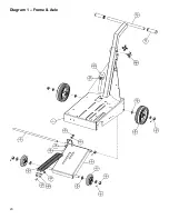
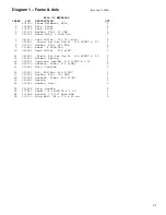
Page 20: ...20 Diagram 1 Frame Axle...
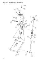
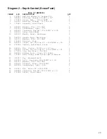
Page 22: ...22 Diagram 2 Depth Control Screw Feed...
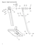
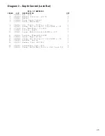
Page 24: ...24 Diagram 3 Depth Control Lock Bar...
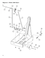
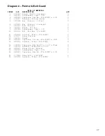
Page 26: ...26 Diagram 4 Pointer Belt Guard...
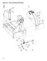
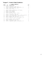
Page 28: ...28 Diagram 5 Guards Water Distribution...
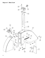
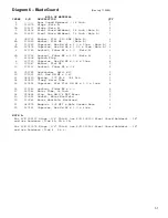
Page 30: ...30 Diagram 6 Blade Guard...
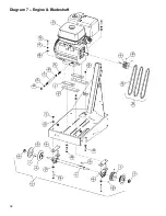
Page 32: ...32 Diagram 7 Engine Bladeshaft...
Page 34: ...34 Diagram 8 Electric Motor...
Page 36: ...36 Diagram 9 Air Motor...
Page 39: ...39 NOTE NOTA...


