26
TASCAM Model 24
2 – Names and Functions of Parts
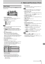
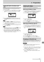
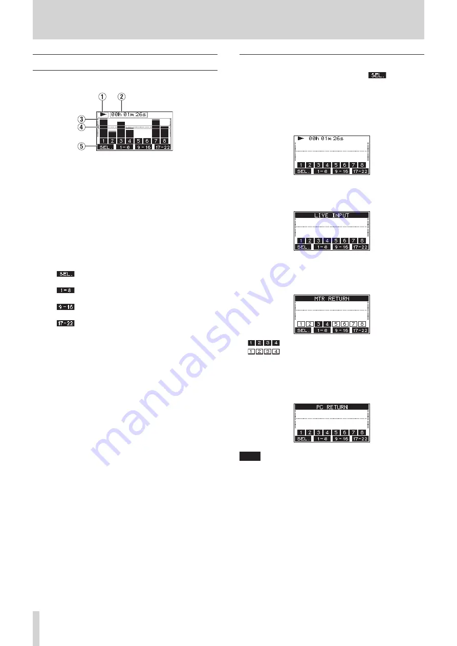
Meters Screen
This shows the levels of the signals being input to the unit.
1
Transport status
This icon shows the recorder operation status.
2
Recorder time counter
This shows the elapsed time from the beginning of the song.
3
Track level meters
These show the signal levels of each channel.
4
Level meter guide
This provides guidance for level adjustment. The guide is
shown at the -12dB level.
5
Function button functions
This shows the functions assigned to the function button on
the Meter Screen.
i
F1
Press to change the input sources shown on
the Meter Screen.
i
F2
Press to show the level meters for channel
1–8 signals on the Meter Screen.
i
F3
Press to show the level meters for channel
9–16 signals on the Meter Screen.
i
F4
Press to show the level meters for channel
17–22 and MAIN MIX L/R bus signals on the
Meter Screen.
Meter Screen details
When the Meter Screen is open, press the
F1
button to
change the signal sources shown by the meters.
Channel input level screens
The levels of signals input on each channel are shown depend-
ing on their
MODE
switch settings.
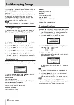
LIVE INPUT Screen
This shows the levels of signals being input to the input jacks.
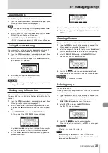
MTR RETURN Screen
This shows the playback signal levels of songs recorded on SD
cards.
Channels that have recording data in the song
Channels that do not have recording data in the
song
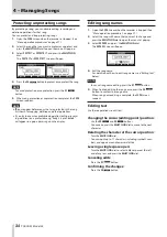
PC RETURN Screen
This shows the levels of signals output from a computer when
used as a USB audio interface.
NOTE
Output from the computer, including from Windows Media
Player and iTunes, is sent to channels 1-2.
Summary of Contents for 24
Page 160: ...160 TASCAM Model 24 Block diagram Sch ma fonctionnel Diagrama de bloques...
Page 162: ......


