background image

  TASCAM CC-222 Owner’s Manual 

3

CAUTION:

Read all of these Instructions.

Save these Instructions for later use.

Follow all Warnings and Instructions marked on the audio
equipment.

1) Read Instructions

 — All the safety and operating instructions should

be read before the product is operated.

2) Retain Instructions 

— The safety and operating instructions should

be retained for future reference.

3) Heed Warnings

 — All warnings on the product and in the operating

instructions should be adhered to.

4) Follow Instructions

 — All operating and use instructions should be

followed.

5) Cleaning

 — Unplug this product from the wall outlet before cleaning.

Do not use liquid cleaners or aerosol cleaners. Use a damp cloth for clean-
ing.

6) Attachments

 — Do not use attachments not recommended by the

product manufacturer as they may cause hazards.

7) Water and Moisture

 — Do not use this product near water — for

example, near a bath tub, wash bowl, kitchen sink, or laundry tub; in a wet
basement; or near a swimming pool; and the like.

8) Accessories

 — Do not place this product on an unstable cart, stand,

tripod, bracket, or table. The product may fall, causing serious injury to a
child or adult, and serious damage to the product. Use only with a cart,
stand, tripod, bracket, or table recommended by the manufacturer, or sold
with the product. Any mounting of the product should follow the manufac-
turer’s instructions, and should use a mounting accessory recommended by
the manufacturer.

9)

 A product and cart combination should be moved with care. Quick stops,

excessive force, and uneven surfaces may cause the product and cart com-
bination to overturn.

10)


Ventilation

 — Slots and openings in the cabinet are provided for ven-

tilation and to ensure reliable operation of the product  and to protect it
from overheating, and these openings must not be blocked or covered. The
openings should never be blocked by placing the product on a bed, sofa,
rug, or other similar surface. This product should not be placed in a built-in
installation such as a bookcase or rack unless proper ventilation is provided
or the manufacturer’s instructions have been adhered to.

11) Power Sources

 — This product should be operated only from the

type of power source indicated on the marking label. If you are not sure of
the type of power supply to your home, consult your product dealer or local
power company. For products intended to operate from battery power, or
other sources, refer to the operating instructions.

12) Grounding or Polarization

 — This product may be equipped with a

polarized alternating-current line plug (a plug having one blade wider than
the other). This plug will fit into the power outlet only one way. This is a
safety feature. If you are unable to insert the plug fully into the outlet, try
reversing the plug. If the plug should still fail to fit, contact your electrician
to replace your obsolete outlet. Do not defeat the safety purpose of the
polarized plug.

13) Power-Cord Protection

 — Power-supply cords should be routed so

that they are not likely to be walked on or pinched by items placed upon or
against them, paying particular attention to cords at plugs, convenience
receptacles, and the point where they exit from the product.

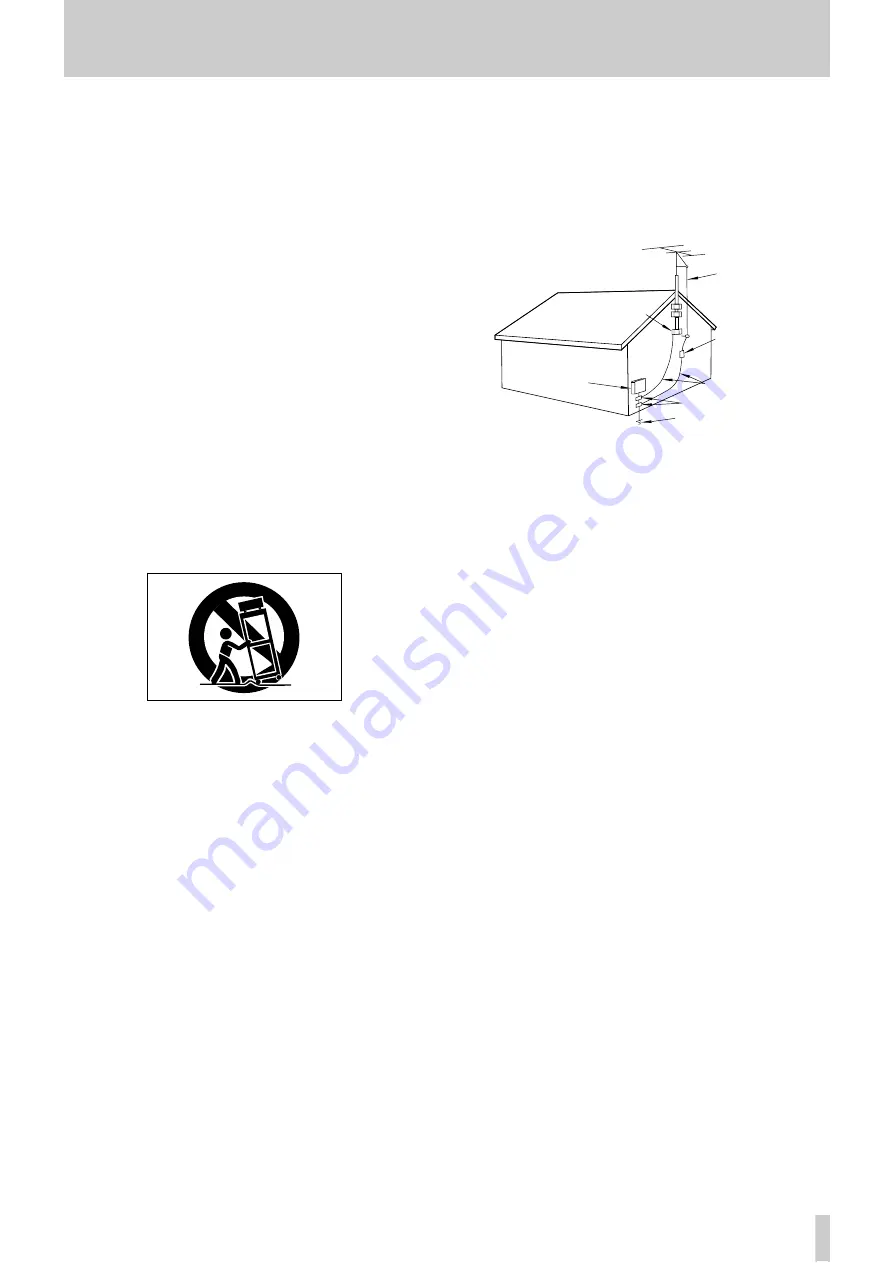
14) Outdoor Antenna Grounding

 — If an outside antenna or cable

system is connected to the product, be  sure the antenna or cable system is
grounded so as to provide some protection against voltage surges and built-
up static charges. Article 810 of the National Electrical Code, ANSI/NFPA
70, provides information with regard to proper grounding of the mast and
supporting structure, grounding of the lead-in wire to an antenna discharge
unit, size of grounding conductors, location of antenna-discharge unit, con-
nection to grounding electrodes, and requirements for the grounding elec-
trode.

"Note to CATV system installer:

This reminder is provided to call the CATV system installer’s attention to
Section 820-40 of the NEC which provides guidelines for proper grounding
and, in particular, specifies that the cable ground shall be connected to the
grounding system of the building, as close to the point of cable entry as
practical.

15) Lightning

 — For added protection for this product during a lightning

storm, or when it is left unattended and unused for long periods of time,
unplug it from the wall outlet and disconnect the antenna or cable system.
This will prevent damage to the product due to lightning and power-line
surges.

16) Power Lines

 — An outside antenna system should not be located in

the vicinity of overhead power lines or other electric light or power circuits,
or where it can fall into such power lines or circuits. When installing an
outside antenna system, extreme care should be taken to keep from touch-
ing such power lines or circuits as contact with them might be fatal.

17) Overloading

 — Do not overload wall outlets, extension cords, or

integral convenience receptacles as this can result in risk of fire or electric
shock.

18) Object and Liquid Entry

 — Never push objects of any kind into

this product through openings as they may touch dangerous voltage points
or short-out parts that could result in a fire or electric shock. Never spill
liquid of any kind on the product.

19) Servicing

 — Do not attempt to service this product yourself as open-

ing or removing covers may expose you to dangerous voltage or other
hazards. Refer all servicing to qualified service personnel.

20) Damage Requiring Service

 — Unplug this product from the wall

outlet and refer servicing to qualified service personnel under the following
conditions:

a)

when the power-supply cord or plug is damaged.

b)

if liquid has been spilled, or objects have fallen into the product.

c)

if the product has been exposed to rain or water.

d)

if the product does not operate normally by following the operating

instructions. Adjust only those controls that are covered by the operating
instructions as an improper adjustment of other controls may result in
damage and will often require extensive work by a qualified technician to
restore the product to its normal operation.

e)

if the product has been dropped or damaged in any way.

f )

when the product exhibits a distinct change in performance – this

indicates a need for service.

21) Replacement Parts

 — When replacement  parts are required, be

sure the service technician has used replacement parts specified by the
manufacturer or have the same characteristics as the original part. 
Unauthorized substitutions may result in fire, electric shock, or other
hazards.

22) Safety Check

 — Upon completion of any service or repairs to this

product, ask the service technician to perform safety checks to determine
that the product is in proper operating condition.

23) Wall or Ceiling Mounting

 — The product should be mounted to a

wall or ceiling only  as recommended by the manufacturer.

24) Heat 

— The product should be situated away from heat sources such

as radiators, heat registers, stoves, or other products (including amplifiers)
that produce heat.

ANTENNA
LEAD IN
WIRE

ANTENNA
DISCHARGE UNIT
(NEC SECTION 810-20)

G

ROUNDING CONDUCTORS

(NEC SECTION 810-21)

GROUND CLAMPS

POWER SERVICE GROUNDING
ELECTRODE SYSTEM
(NEC ART 250. PART H)

NEC - NATIONAL ELECTRICAL CODE

ELECTRIC
SERVICE
EQUIPMENT

Example of Antenna Grounding as per

National Electrical Code, ANSI/NFPA 70

GROUND
CLAMP

IMPORTANT SAFETY INSTRUCTIONS

Summary of Contents for CC-222

Page 1: ...erature accompanying the appliance The lightning flash with arrowhead symbol within an equilateral triangle is intended to alert the user to the presence of uninsulated dangerous voltage within the pr...

Page 2: ...l device pursuant to Part 15 of the FCC Rules These limits are designed to provide reasonable protection against harmful interference when the equipment is operated in a commercial environment This eq...

Page 3: ...pporting structure grounding of the lead in wire to an antenna discharge unit size of grounding conductors location of antenna discharge unit con nection to grounding electrodes and requirements for t...

Page 4: ...nd is classified as a class 1 laser product There is no hazardous invisi ble laser radiation during operation because invisible laser radiation emitted inside of this product is completely confined in...

Page 5: ...ures 18 Tape counter 18 Pitch control 18 Fast forward and rewind 19 Search keys 19 4 CD player Simple playback operations 20 Time display modes 20 Track search 20 Playback modes 21 Programmed order pl...

Page 6: ...ulti dial is used to set and con firm parameter settings A convenient wireless remote control unit provides additional functionality and permits the operation of the unit from a distance NOTE This pro...

Page 7: ...e than 5 degrees away from the horizontal the tray will not open or close The voltage supplied to the unit should match the voltage as printed on the rear panel If you are in any doubt regarding this...

Page 8: ...l include one of the following logos However you should note that an audio CD created using a CD RW disc may not play back satisfactorily on every audio CD player It will naturally be play able on the...

Page 9: ...onal notes with regard to CD R and CD RW discs There are additional precautions that you should take when handling CD R and CD RW discs that are dif ferent to those that you should take when handling...

Page 10: ...f time remove the batter ies Old batteries can leak casing damage to the remote control unit Always dispose of old batteries in the way recom mended by your local garbage disposal authorities About th...

Page 11: ...urces etc C RESET key Resets the tape counter to zero D RTZ key Returns the tape to the zero position E INPUT 2 SEL key Repeated presses of this key cycle between the different sources available for t...

Page 12: ...nal playback and recording or or continuous playback only not recording X Dolby NR OFF ON switch Use this switch to turn the Dolby noise reduction off and on for the cassette deck Y CD TAPE CONT PLAY...

Page 13: ...t a record deck to the CC 222 The destination of the signal is determined by a menu item Connect the earth grounding wire of the record deck to the GND terminal NOTE It Do not connect a record deck to...

Page 14: ...op J MENU key Performs the same functions as R K ENTER key Performs the same functions as pushing the MULTI DIAL S L Number keys 0 through 10 10 and CLEAR Used for entering track numbers for disc play...

Page 15: ...ith the amplifier s vol ume control 6 To stop playback press the STOP key Continuous tape CD playback 1 Load the tape as described above to be played back into the unit Load the disc use the OPEN CLOS...

Page 16: ...e PLAY key whose indicator is lit is pressed recording will restart If the PLAY key whose indicator is unlit is pressed the recording direction will reverse and the PLAY key must be pressed again to r...

Page 17: ...E key to pause playback at the point where the playback is to start 3 If recording is to start at the beginning of the cassette make sure the cassette is stopped otherwise locate the cassette to the a...

Page 18: ...econds of silence will be recorded on the tape and the deck will return to record pause mode If the REC MUTE key is held and pressed for longer than four seconds while recording is in progress silence...

Page 19: ...rch forward or backward by the appropriate number of items The tape counter value is replaced by CPxx if searching forward and CP xx when searching backwards Note that the terms forwards and backwards...

Page 20: ...he current track number is given fol lowed by the time as given below e g 10Tr 0 48 Press the DISPLAY key to cycle through these time display modes as described here NOTE If programmed playback has be...

Page 21: ...on page 21 below The red PROGRAM display indi cator lights in this mode The selected mode is shown in large characters dis appears from the display a few seconds after select ing the mode and the dis...

Page 22: ...t the display shows Repeat OFF and the REPEAT indicator goes out Pressing STOP also cancels repeat mode Setting the A and B repeat points While the REPEAT A B indicator is lit you can set the points b...

Page 23: ...s function is only available from the remote control unit It is not possible to use this function with the main unit only If you press the AUTO SPACE key while the play back is automatically paused be...

Page 24: ...AL or the SKIP keys to adjust the input level The maximum boost is 18db relative to the original input level and the signal may be cut by up to 60dB There is also a setting which repre sents a complet...

Page 25: ...isc 3 Adjust the level of the source s following the guidelines in Signal volume on page 24 NOTE The red OVER indicators on the meters should never light Unlike analog equipment digital audio units pr...

Page 26: ...ength and there can be a maximum of 99 tracks on an audio CD Bear these limitations in mind when adding track divisions Restricting the number of tracks When making a recording using the CC 222 it is...

Page 27: ...r mode and use the INPUT 1 SEL key to select TAPE You can also stop the dubbing process by pressing either of the STOP keys these are the only keys which will work in dubbing mode NOTE A recordable di...

Page 28: ...disc from the RIAA PHONO source This is the same as the standard manual recording procedure Basic recording on page 25 except that the PHONO input option should be selected INPUT 1 SEL key before reco...

Page 29: ...onized recording stops are when recording digitally an appropriate digital sig nal is detected If the signal is detected from a CD the unit enters record ready mode after 2 seconds If the signal is de...

Page 30: ...dy mode The time between the stopping of the source and entering record ready mode is used to record a gap at the end of the track 3 If no changes are made to the unit s controls restarting the source...

Page 31: ...he analog connections since the track divisions are deter mined by relative silence it is possible that spurious track divisions will be inserted Under these conditions it may be better to use manual...

Page 32: ...the set input level Signal volume on page 24 and fade outs go from the current input volume to silence The fade in and fade out times can be set indepen dently in increments of one second from 1 seco...

Page 33: ...c but no digital copies grandchil dren can be made from the child PROH copy prohibited which prevents any digi tal copies being made from the recorded disc 1 Press the MENU key repeatedly until the di...

Page 34: ...ute 10 seconds After finalization a CD RW NO TOC changes to CD RW and a CD R NO TOC changes to a CD NOTE Although CD R discs finalized on the CC 222 may be replayed on ordinary CD players remember tha...

Page 35: ...and the timer starts counting down At the end of the countdown period the word Complete appears briefly on the display and the display returns to the track time display Erasing a whole disc When you w...

Page 36: ...at it contains only recordings that you really want to erase If the refresh operation has been selected the words ERASE XX XX are shown on the display and the timer starts counting down XX XX At the e...

Page 37: ...of the auto space mode pressing the AUTO SPACE key puts the unit into pause mode and playback does not resume automat ically after the auto pause time is elapsed see Auto spacing on page 23 D IN UNLO...

Page 38: ...ng on the power The menu values will be reset The values for INPUT 1 and INPUT 2 are set to LINE 1 and LINE 2 respectively Tray Error Error in the CD tray mechanism Drive Error Error in the CD drive m...

Page 39: ...8 TYPE II Digital outputs COAXIAL RCA pin IEC60958 TYPE II OPTICAL TOSLINK IEC60958 TYPE II LINE INPUTS 1 Unbalanced RCA Nominal input level 10 dBV 6dBV 16 dB Maximum input level 6dBV Input impedance...

Page 40: ...Cartridge type MM moving magnet Input signal level 5 6mV Input impedance 47 k Signal to noise ratio 60 dB PHONES headphone output 6 mm 1 4 stereo Output level 10 mW 10 mW into 32 Voltage requirements...

Page 41: ...pinch roller using rubber cleaning fluid Both fluids are available in TEAC Tape Cleaning Kits HC 2 and RC 2 in the U S A or TZ 261 in other areas Demagnetizing heads Be sure that the power is off then...

Page 42: ...s Park Watford Hertfordshire WD1 8TE U K TEAC DEUTSCHLAND GmbH Phone 0611 71580 Bahnstrasse 12 65205 Wiesbaden Erbenheim Germany TEAC FRANCE S A Phone 01 42 37 01 02 17 Rue Alexis de Tocqueville CE 00...

Reviews: