background image

15

TASCAM  CD-200/CD-200i

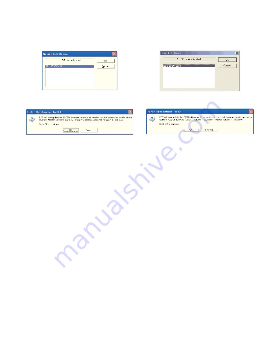
10.When [

Select USB Device

] is displayed, select the detect-

ed 

E8a

name and press [

OK

].

11.The firmware writing starts. If the software requires updat-

ing of the 

E8a

firmware, follow the instruction. 

In case the FDT software freezes after the firmware updat-
ing, give up the current firmware writing and reboot the
PC.

12.When the firmware writing completes successfully, turn

the system OFF and unplug the jig cable from it.

13.Finally, restart the product and view the firmware version

to confirm it.

10.

Select USB Device

では、見つかった

E8a

を選択し[

OK

]

を押します。

11.書き込みが始まります。この時、

E8a

のファームウェア更新

を求められる場合がありますので指示に従ってください。

その際、ファームウェア更新後にFDTがフリーズする場合が
あります。その場合は諦めて一度PCを再起動してください。

12.書き込みが完了したら、製品の電源を切り、製品からジグケ

ーブルを抜きます。

13.最後に製品を起動し、ファームウェアバージョンを表示させ

て確認します。

Summary of Contents for CD-200

Page 1: ...0 5 Message Display glossary 16 6 Block Diagram 18 7 Exploded Views and Parts List 20 8 PC Boards and Parts List 26 9 Included Accessories 39 1 SAFETY INFORMATION 2 2 3 3 6 4 10 5 16 6 18 7 20 8 26 9...

Page 2: ...aser radiation during operation because invisible laser radiation emitted inside of this product is completely confined in the protec tive housings The label required in this regulation is shown at 1...

Page 3: ...Reference Input Level 16 dBV Maximum Input Level 0 dBV Input impedance 22 k ANALOG OUTPUT UNBALANCED Terminal Connector RCA pin jack Reference Output Level 10 dBV Maximum Output Level 6 dBV Output Imp...

Page 4: ...ngs are backed up when the output source is set to CD Time and title display settings CD Playback mode CD Program for loaded CD Current folder for loaded CD Output source setting Repeat setting CD Pit...

Page 5: ...5 TASCAM CD 200 CD 200i Dimensional drawings CD 200i CD 200...

Page 6: ...ays sure to perform the CD pitch con trol potentiometer setting 1 In the test mode menu display n01 PITCH VR and press the REPEAT key 2 When VR CENT is displayed set the potentiometer to the center cl...

Page 7: ...left to the right When the rightmost key in a row has been tested the keys in the next row are tested from the left end toward the right end The last key tested is the PITCH CONTROL key CD 200 or the...

Page 8: ...mber of the microcom puter used in the system 1 Hold down the STOP and REPEAT keys and turn the sys tem ON Continue holding down the two keys until VERSION is displayed After VERSION the version numbe...

Page 9: ...drive is displayed 2 RH is displayed together with the total drive run time count in hours The total drive run time is cleared when EEPROM initial ization For use in factory is performed in the test...

Page 10: ...8a on chip debugging emulator USB connected Jig cable between E8a and system main body board 1 CD 200 CD 50 CD 200i 2 Windows PC OS Windows 2000 Renesas E8a USB E8a Pin No Signals 1 N C 2 Vss 3 N C 4...

Page 11: ...chnology The installation includes the step for confirming the associa tion of file extensions When the following window is dis played check only mot If you do not want association in consideration of...

Page 12: ...ody PCB FRONT J101 using the jig cable 5 Writing the Firmware After connecting the hardware write the firmware in the fol lowing steps 1 Select Start Program Renesas Flash Development Toolkit Flash De...

Page 13: ...devices by entering their names in Filters and then pressing Next CD 200 50 200i R5F2L388B 3 The Communications Port window appears Change the port selected in Select port to E8a and press Next 4 Whe...

Page 14: ...op up click on Browse on the top to view the file selection window In this window move to the folder storing the ROM image file mot file and select the ROM image file to be used 7 Turn the system ON 8...

Page 15: ...E8a firmware follow the instruction In case the FDT software freezes after the firmware updat ing give up the current firmware writing and reboot the PC 12 When the firmware writing completes successf...

Page 16: ...a disc that has MP3 or WAV files NO FILES Lit Lit 7bit ASCII There is no artist data or no data that can be displayed Text information must be 7 bit ASCII compatible text to be displayed 7bit ASCII T...

Page 17: ...TROL PCB Assy An error occurred during communication with the CD drive CD COMM ERR Lit Change the disc The file type is not supported orotherwise could not be played DEC ERR Lit Clean or change the di...

Page 18: ...EEPROM IC DAC AK4384ET MCLK SDATA LRCK BICK CD_RST 14 CTS 78 RTS 3 CD_RXD 2 CD_TXD 1 CD DRIVE CD 5020A POWER SECTION POWER SW DIGITAL OUT SPDIF LINE OUT L SSO 19 SCL 21 DAC_CS 68 DAC_PDN 67 AMUTE 65...

Page 19: ...BNFA MUTE CIRCUIT EEPROM IC DAC AK4384ET MCLK SDATA LRCK BICK CD_RST 14 CTS 78 RTS 3 CD_RXD 2 CD_TXD 1 CD DRIVE CD 5020A POWER SECTION POWER SW DIGITAL OUT SPDIF LINE OUT L SSO 19 SCL 21 DAC_CS 68 DAC...

Page 20: ...and Parts List Exploded View 1 20 TASCAM CD 200 CD 200i 3 Q Q Q Q u t R 4 y r o q q q i w 2 0 E T e e e O z x m Y b n v g l h j f d 5 6 7 s p a W c k 9 8 I U 1 A A B C B B B E E C C D G D C F F G 6 7...

Page 21: ...FRONT CD 200 G 1 21 M02481300B BUTTON OPE CD 160MK2 G 1 22 M02496600A BUTTON B CD 160MK2 G 1 23 B00199008A SCREW BPP 3 8 FZC G 1 24 B00208908A SCREW PPPU 3 8 FZB G 1 25 M01594101A BUTTON SINGLE L N66...

Page 22: ...CD200G EUR Refer to page 34 GATHER PCBA ANALOG CD200 G 1 55 PCB ASSY PHONE CD200 G Refer to page 34 GATHER PCBA ANALOG CD200 G 1 56 PCB ASSY PITCH CD200 G Refer to page 34 GATHER PCBA ANALOG CD200 G...

Page 23: ...D 200 CD 200i 2 1 6 7 8 9 3 O 5 z x b O A G P y o a i u e e p s U Y w T k c v n m l V H t h 0 q q q j f Q W I R E D r S F 4 d g Z Z Z Z C C C C X X L K J N e M 6 7 6 7 6 7 O B G H B C D E H F A B C D...

Page 24: ...24 3M000880 BUSHING 2271 CSA G 2 25 3B0701908A SCREW BTT SSB 4 8 2 26 Y00450000A AC SELECT ASSY CDA550 G ETC 3E040130 SW SL14 22AH 0AN G E01545700A WIRE BROWN 120V CDA550 G E01545800A WIRE BLACK CT C...

Page 25: ...ALOG CD200I G Refer to page 35 GATHER PCBA AN CD200I 2 76 PCB ASSY TRA CD200I JPN G Refer to page 35 GATHER PCBA AN CD200I 2 76 PCB ASSY TRA CD200I T C G Refer to page 35 GATHER PCBA AN CD200I 2 76 PC...

Page 26: ...26 TASCAM CD 200 CD 200i GATHER PCB ANALOG Side A 8 PC Boards and Parts List...

Page 27: ...27 TASCAM CD 200 CD 200i GATHER PCB ANALOG Side B...

Page 28: ...28 TASCAM CD 200 CD 200i GATHER PCB FRONT Side A...

Page 29: ...29 TASCAM CD 200 CD 200i GATHER PCB FRONT Side B...

Page 30: ...30 TASCAM CD 200 CD 200i GATHER PCB CD200i SideA...

Page 31: ...31 TASCAM CD 200 CD 200i GATHER PCB CD200i SideB...

Page 32: ...32 TASCAM CD 200 CD 200i GATHER PCB CD200i 2 SideA...

Page 33: ...33 TASCAM CD 200 CD 200i GATHER PCB CD200i 2 SideB...

Page 34: ...G L204 E0157480 FILTER FER K5A RH35 0 8 G L205 E0157480 FILTER FER K5A RH35 0 8 G Q200 S0074832 TRANSISTOR KTC2874BAT PG Q201 S0069232 TRANSISTOR DTA124ESATP G Q202 S0069222 TRANSISTOR DTC124ESATP G...

Page 35: ...G J209 E01553700B HARNESS ASSY F PW CD200 G J210 E0156820 CONNECTOR B 5B EHA LF G J212 E01555400C HARNESS ASSY DPW CD200 G L201 E0126520 FILTER DSS6NB32A101Q91A G L202 E0130740 COIL 10UH 3 6A DR2W8 7...

Page 36: ...E01588900A HARN ASSY F GND CD200 G PCB ASSY PW SW CD200 G C40 E0122630 SPK KILLER CS12 F2GA472MYAS G P40 E0112450 CONNECTOR B2P3VH LF SN G SW40 E0128290 SW SFDLB11L7U TK G E95374000A GATHER PCBA FRON...

Page 37: ...S2318 0100F G J851 E0125414 CONNECTOR S 5B ZR 3 4 G U850 E0124074 FILTER EXCCET101U G U851 E0124074 FILTER EXCCET101U G AUX_GND E01588900A HARN ASSY F GND CD200 G E95373900A GATHER PCBA CD 200I 2 G PC...

Page 38: ...DESCRIPTION WIRE SECT CD200I G CD 200i only REF NO PARTS NO DESCRIPTION TASCAM CD 200 CD 200i 38 E01554400B HARNESS ASSY DR CD200 G E01554400B HARNESS ASSY DR CD200 G E01597000A HARN ASSY AUX CD200I...

Page 39: ...MNL S CD 200I G E 3M0028300A ASSY RACK MOUNT SCREW KIT SCREW BPA M5X12 NI WASHER FIBER BLK E01602200A RMT CONT RC CD200I G E0155040 BATTERY UM 3 2P X ED G TASCAM CD 200 CD 200i 4 Included Accessories...

Reviews: