−18−
TASCAM MD-CD1 & LA-MC1
2
Pit Disc adjustment
1) When "FBIAS ADJUAST" is displayed as a result of
completing adjustment
1
, take out MMD-221 and insert
MMD-111 instead.
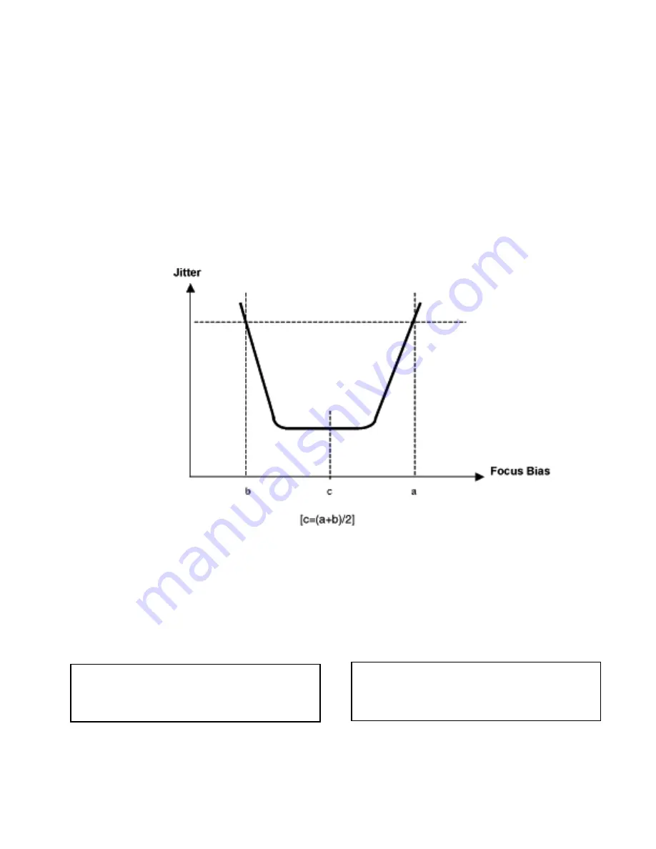
2) Make adjustment at points "a" and "b" in a similar way as
in
1
(25 ns: slightly exceeded C1=<220>)
Ú
Making MO Disc adjustment affects the Pit Disc adjustment. Be
sure to make the Pit Disc adjustment after making the MO Disc
adjustment.
Ú
In the process of adjustment, the Track Number area in the
display shows Cluster Address in hexadecimals.
2
Pit Discの調整
1)
1
に 続 い て 、「 F B I A S A D J U S T 」 表 示 し た ら 、
MMD-211を取り出し、MMD-111挿入して下さい。
2)以下、
1
と同様に、a、b Pointの調整を行って下さ
い。(ジッターメータ値が25ns(C1=<220>を丁
度超えた値)
※ MO Discの調整を行うと、Pit Discの調整値も更新
されてしまいます。MO Discの調整を行った場合、
必ずPit Discの調整も行って下さい。
※ 調整中、ディスプレイ上のTrack Number Areaには
再生中のCluster AddressをHex表示しています。
● MO Discの自己録確認ーパワー確認(
「LDPWR
CHECK」
)
ジッターメータのプローブをRF端子に接続して下さい。
ジッターメータが無い場合、ディスプレイに表示される
「C1」を<>内の値で確認して下さい。ジッターメータ
を使用しての確認を推奨します。
確認途中で、「CD STOP」キーを押すと、調整を中断し
「MD ADJUST」に戻ります。
注意事項
レーザーダイオード保護の為、記録は10秒以内で終了
する事。
1
1倍速の確認
1)
「 M U L T I J O G 」、「 E N T E R 」 キ ー で 、「 M D
ADJUST」
∑
「CREC MODE」
∑
「CREC OUT x
1」をディスプレイ上に表示させて下さい。
2)
「CREC OUT x1」表示したら、SONY MDW-74、
または相当品を挿入して下さい。
Caution:
To protect the laser diode, recording should be completed
within 10 seconds.
º
Checking MO Disc self-record
Connect the jitter meter probe to the RF terminal.
If no jitter meter is available, check value C1 displayed against
what is shown within angle brackets.
We recommend using a jitter meter.
If the CD STOP key is pressed in the process, the checking is
interrupted, bringing you back to "MD ADJUST".
1
1X speed check
1) Using the multi-jog and the ENTER key, select "MD
ADJUST"
∑
"CREC MODE"
∑
"CREC OUT x1" on the
display.
2) When "CREC OUT x1" is displayed, insert SONY MDW-74
or equivalent disc.


