MMR-8 Tascam MMR-8 Owner’s Manual • Chapter 1 • General Information
10
The MMR-8 will directly play back material created on Digidesign Pro Tools
or WaveFrame
digital
audio workstations, as well as OMF Compositions which reference Sound Designer II audio media files.
The disk drive or drives containing edited Session, Project, or OMF files are simply “unplugged” from
the workstation and then “hot-plugged” into the MMR-8, using the standard internal Kingston hard drive
carrier, or otherwise connected to the MMR-8’s external SCSI port. Once the drive(s) are mounted by the
MMR-8, tracks from one or more projects may be loaded as required for the mix session. Sound files of
the same or different audio formats may thus be played back simultaneously from one or more drives.
When the MMR-8 is turned on for the first time, the system default operating parameters are installed,
and the machine is placed into the Normal state (see the Functional Overview below). Users can also save
up to ten settings files that have MMR-8 parameters “customized” or set for a particular application.
These settings files are stored on the internal hard drive so that they can be used to instantly reconfigure
the MMR-8 between mix sessions. The MMR-8’s operating parameters can be manually changed before
or even during a mix session, through menu selections. Optional password protection may be used to
prevent some parameters from being changed inadvertently.
Hardware Overview
The MMR-8 comes standard with one removable Kingston drive carrier. The Kingston carrier can hold a
standard SCSI drive for recording and playback of audio tracks. An internal IDE hard drive holds the
operating system, the MMR-8 software, and the parameter settings files. Additional external SCSI drives
can be connected and (after power-up) accessed by the MMR-8. This eliminates having to pre-combine
tracks from multiple drives onto a single drive. A list of approved media drives is given in Appendix B.
The MMR-8 is based on a standard Intel Pentium™ processor-based PC motherboard, with integral PCI
and ISA bus slots running under an industry-standard operating system. The MMR-8 DSP,
synchronization, and audio interface boards plug directly into this PC motherboard. There is a Lithium
battery #CR2032 for the CMOS circuit on the motherboard.
Caution: Battery May Explode if
Mistreated. Do Not Recharge, Disassemble or Dispose of in Fire.
The MIC (MMR-8 analog-to-digital
Input Converter) and MOC (MMR-8 digital-to-analog Output Converter) boards are in their own shielded
cage, connected to the AIO (Analog I/O) card via ribbon cables. The PRX (DSP) card performs the audio
processing for the MMR-8. A standard Symbios SCSI-2 controller card also plugs into the PCI bus. The
Sync card, the UI/B (User Interface/Biphase) card, the AIO (analog I/O) card, and the DIO (AES/EBU
digital I/O) card are all plugged into the ISA bus. The Biphase Operations Board (BOB) occupies a slot
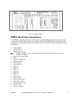
on the back panel to provide connections for the system’s four Biphase inputs and one Biphase output. It
is attached to the UI/B card via a ribbon cable and is not plugged into a slot.
Very high quality 20-bit converters on all analog inputs and outputs assure excellent audio fidelity. The
MMR-8 uses 24-bit internal digital resolution for all digital audio processing. Recorded audio is stored in
standard linear 16-bit or 24-bit sound files. The MMR-8 can read StudioFrame or WaveFrame sound files
as well as Sound Designer II files, AIFC files, and .WAV files, all in either 16 or 24-bit resolution.
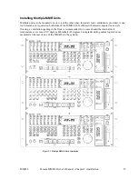
The MMR-8 front panel contains 45 soft-touch keys with most of the common dubber and audio playback
functions available through one or two keystrokes. There are also seven large illuminated motion control
buttons (Play, Stop, FF, Rew, Reverse Play, Record, Rehearse) for track playback and “play head”
locating, and an Online button for setting the MMR-8 offline (as a local machine) or online (as a
synchronized slave or a master machine). When the MMR-8 is the master and is online, then any number
of external SMPTE/EBU, MTC or biphase devices will follow the MMR-8. When the MMR-8 is set as a
slave, it can chase time code, biphase, a TimeLine Lynx™ module, or another MMR-8.
Summary of Contents for MMR-8
Page 5: ......
Page 6: ......
Page 7: ......
Page 8: ......
Page 9: ......
Page 38: ...32 Tascam MMR 8 User s Guide Chapter 3 MMR 8 Operation MMR 8...
Page 42: ...36...
Page 94: ...Tascam MMR 8 Owner s Manual Appendix A Control Panel Summary 88...
Page 110: ...Tascam MMR 8 Owner s Manual Appendix E Glossary 104...


