MMR-8
Tascam MMR-8 Owner’s Manual • Chapter 2 • Installation
21
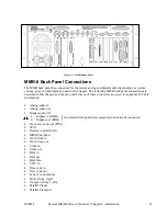
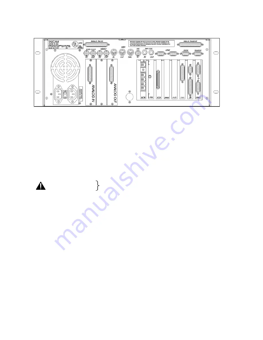
Figure 2-3. MMR-8 Back Panel
MMR-8 Back Panel Connections
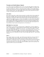
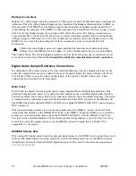
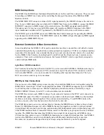
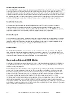
The MMR back panel has connectors for the system analog and digital audio input/output, as well as
various types of synchronization and control signals. The following MMR back panel connections are
described in this chapter, and the pin outs for many of these connectors are given in Appendix D: Cable
Information.
•
Analog audio in
•
Analog audio out
•
Digital audio I/O
•
Biphase in (BOB)
•
Biphase out (BOB)
•
Mono mix audio out (PRX)
•
SCSI
•
Remote control (UI/B)
•
MMR bus (Sync)
•
Word clock in
•
Word clock out
•
Video in
•
Video out
•
Midi in
•
Midi out
•
Midi thru
•
VITC in
•
Time code in
•
Time code out
•
Lynx (2 connections)
•
Editor (Sony 9-pin)
•
Transport (Sony 9-pin)
•
Parallel Tracks
•
Parallel Transport
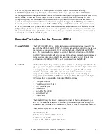
Not intended for public telecommunication network connection
Summary of Contents for MMR-8
Page 5: ......
Page 6: ......
Page 7: ......
Page 8: ......
Page 9: ......
Page 38: ...32 Tascam MMR 8 User s Guide Chapter 3 MMR 8 Operation MMR 8...
Page 42: ...36...
Page 94: ...Tascam MMR 8 Owner s Manual Appendix A Control Panel Summary 88...
Page 110: ...Tascam MMR 8 Owner s Manual Appendix E Glossary 104...


