background image

Whether your studio is digital or analog, there are a few things you need to know before really getting

into any recording.  When digital audio devices are linked together, it is imperative that the user

understand terms like word clock, sample rate, and bit rate.  So, here’s a crash course in digital audio.

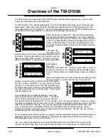
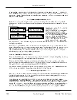
Recovering

Sample Data

0000000000000000

----- OVER -----

1000000000000000

0001000000000000

0010000000000000

0011000000000000

0100000000000000

0101000000000000

0110000000000000

0111000000000000

1001000000000000

1010000000000000

1011000000000000

1100000000000000

1101000000000000

1110000000000000

1111000000000000

1 2 3 4 5 6 7 8 9 10 11 12 13 14 15 16 17 18 19 20 21 22 23 24 25 26 27 28 29 30 31 32 33 34 35 36 37 38 39 40 41 42 43 44 45 46 47 48

Sampling 1/1000th

Second of Audio

Reconstructing

Waveform

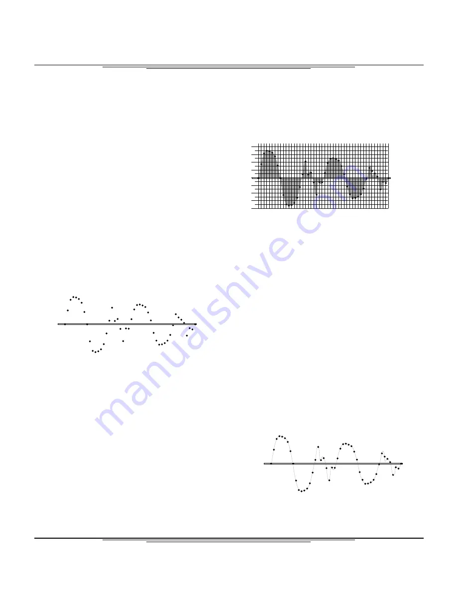
The first thing we need to explain is what this

squiggly line that everyone always draws

actually represents.  For the physics buffs, this

displays force over time.  For the rest of the

world, think of this line as the path the speaker

diaphragm will take to reproduce the sound.  If

you put a ruler vertically across the wave, and

drag the paper across underneath the ruler

horizontally, the waveform line tells you where

the speaker moves when making that sound.

Digital audio converters are kind of like a

movie projector on 15 cups of Starbucks

coffee.  In a movie, the moving picture is made up of a series of still images flashed by you at a rate of

24 to 30 frames a second.  But remember, each picture is a still image.  In audio, we are examining the

waveform at a rate of 44,100 times per second (44.1kHz) or 48,000 times per second (48kHz.)  The

number of times per second we are examining the sound wave is our sample rate.

Each time the waveform is examined, the position of the

waveform is recorded with a binary number, called a

word.  The number of digits in the word is your bit rate.

(Each digit is one “bit”.)  For instance,

0100110100111001 is a 16 bit word, because it has 16

digits in it.  011010001011110100110010 is a 24 bit

word, because it has 24 digits in it.

When it comes time to convert the digital signal back into

analog, the sample data must be reconstructed.  The

data itself is simply storing the location of the sound

wave at a given interval.

Once the data is recovered, the waveform is reconstructed.  This is a big game of dot-to-dot, except the

converters are typically armed with some fancy mathematical symbols that round out the edges.  Once

that’s done, you’ve got your sound back!

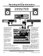
So, the two main aspects of a digital signal are the sample

rate, and the word length AKA bit rate.  The word length of

each device can vary because most digital devices can

truncate extra digits out, or fill blank spaces in with more

zeros. But, the sample rate must remain the same when the

connection is made digitally.  In fact, the sample rate not

only needs to be the same, but the sample rate needs to be

synchronized between all the units.

The sample rate is synchronized by utilizing a word clock

master.  One device in the chain will be designated the

master, and the others will follow.  Some digital lines

are internally clocked, meaning they carry word clock information within the line.  Others will require

separate word clock lines.  On the next three pages you will find diagrams for some common hook-ups

for the TM-D1000, as well as instructions for setting the word clock status on your TM-D1000 mixer.

Section II

Crash Course in Digital Audio

TASCAM TM-D1000 Tutorial

1/99

Section II, page 1

Summary of Contents for TM-D1000

Page 1: ...00 QuickStart MIDI Implementation What the Heck is That Optional Accessories for the TM D1000 Troubleshooting the TM D1000 TASCAM TM D1000 The Purpose of this Tutorial The TM D1000 Digital Mixer Tutor...

Page 2: ...on the TM D1000 The built in card offers 4 slots of processing Dynamics i e compressors and expanders take one slot Stereo effects i e reverb flange delay etc take two slots After you ve slaved over...

Page 3: ...st Pre Post Pre Post EQ In Out Freq Freq Freq Freq Freq Freq Freq Freq Freq Freq Freq Freq Gain Gain Cue Gain MUTE Pan L R 1 2 3 4 Direct Trim Pad Aux 2 Aux 4 Aux 1 Aux 3 Pre Post Pre Post Pre Post Pr...

Page 4: ...umber of times per second we are examining the sound wave is our sample rate Each time the waveform is examined the position of the waveform is recorded with a binary number called a word The number o...

Page 5: ...nced cable from your monitor outputs not your stereo outputs to the power amplifier for your monitor speakers 5 If you have a mixdown deck with a digital input connect your mixdown deck to Digital Out...

Page 6: ...t on your multitrack For an ADAT push Digital In or Digital Input depending on the vintage of your ADAT For other lightpipe machines consult that machine s manual for settings 5 Connect a balanced cab...

Page 7: ...tape at 48kHz then use Word Sync In 48k If you don t know which sample rate you selected for your machine there are two indicator lights on the DA 88 just to the right of the tape eject button labell...

Page 8: ...t 8 channel strips Not all of these are accessible right off the bat we ll cover that soon The EQ and aux controls are accessed in the display window Simply press the PARAM SEL button to scroll throug...

Page 9: ...ATA ENTRY dial to the left will bring us back to the first screen of the EQ Note The following walk through assumes you have not changed the mixer from the factory default configuration To get to the...

Page 10: ...pecific effects easier the top line gives you the name of the effect while the bottom line will tell you what the effect is i e reverb delay flange chorus etc Once you ve found the effect you wish to...

Page 11: ...sfade The panning EQ aux etc will all snap as soon as the next scene is recalled Rotate the DATA ENTRY dial to determine the transition time between scenes then press ENTER The scene is now stored in...

Page 12: ...ther and auxiliaries to send to effects We thought of that too You can assign two paths as busses and two as auxiliaries Basically the rule of thumb is Your different bussing aux options are 4 aux sen...

Page 13: ...ctly access these combinations 1 Press SHIFT and PARAM SEL simultaneously Option MODE 2 Rotate the DATA ENTRY dial to MODE Press ENTER MODE BUSS Function Select 3 Rotate the DATA ENTRY dial to BUSS Fu...

Page 14: ...der de esser and exciter Effect 2 same as Effect 1 plus reverb and gated reverb 4 Dyn Channels Effect Pattern Ch Dynamics Aux 1 Aux 2 Master L Master R Eff2 Eff1 Effect Pattern L R Eff1 Aux1 2 Eff2 Au...

Page 15: ...as Effect 3 For this reason you really won t see Effect 3 in any set up menus Again as mentioned in the previous section stereo effects assigned to aux sends need to be returned somewhere Channel dyna...

Page 16: ...ern Ch Dynmcs Aux1 2 Para 4 Dyn Channels Aux 1 Aux 2 Eff2 Eff1 Effect Pattern Ch Dynmcs Aux1 2 Aux3 4 4 Dyn Channels Aux 1 Aux 2 Aux 3 Aux 4 Eff2 Eff5 Effect Pattern Aux 1 2 Aux3 4 Mono L R Eff5 Aux 1...

Page 17: ...eo Effect 5 in parallel on Aux 3 4 Stereo Effect 2 cascaded into Stereo Effect 1 on Aux 1 2 Stereo Effect 5 on Aux 3 4 Stereo Effect 4 on L R Master Stereo Effect 2 cascaded into Stereo Effect 1 casca...

Page 18: ...the next page If you are assigning channel dynamics then continue below The built in effects processor is now set up for your processing slots but the individual dynamics still need to be assigned to...

Page 19: ...manual where it details all of the effect possibilities what happens if you don t carry this manual with you everywhere you go It is possible to simply ask the mixer what effect processors are assign...

Page 20: ...uss 2 feeds tracks 2 and 6 Buss 3 feeds tracks 3 and 7 and buss 4 feeds tracks 4 and 8 The track that the buss is recorded to is determined by the multitrack Simply by enabling Record on that channel...

Page 21: ...EBU signal The digital output can be assigned to the buss aux sends or to the L R output The digital input can be assigned to any channel the EFFECT RETURN or the AUX INPUT User Tip If you are assign...

Page 22: ...Setup Press ENTER Setup Digital Input Rotate the DATA ENTRY dial to Digital Input Press ENTER Digital Input A RCA Rotate the DATA ENTRY dial to select which digital format you wish to use Press ENTER...

Page 23: ...00 can be linked with MIDI equipped lighting consoles or show automation equipment Since the Auxiliaries are independently assignable to be pre or post fader you can set up great monitor mixes from th...

Page 24: ...0 doubles your processing capability For more information see Section XIV Optional Accessories for the TM D1000 The built in snapshot capability can make mixing your song much easier You can set up se...

Page 25: ...n Getting signal into the channel Plug a microphone guitar keyboard or another sound source into channel 1 Raise the fader of channel 1 to the 0 on the channel strip Raise the Trim control for channel...

Page 26: ...it s L R routing by pressing the lit L R button Again the L R button will turn off when you do this and you will no longer be able to hear the signal directly Of course if the light is already out th...

Page 27: ...MIX mode To do that Press SHIFT and PARAM SEL together The top line of the screen should read Option If it does not press ESCAPE until it does Rotate the DATA ENTRY dial to the left until the bottom l...

Page 28: ...ess SHIFT To get to another space simultaneously press down and rotate the DATA ENTRY dial When you re done naming your snapshot Press ENTER The screen will now allow you to set the transition time be...

Page 29: ...an EQ change the delay from multi tap to stereo etc Simply have your sequencer recording when you change the parameter Be aware however that the mixer sends and receives information across all 16 MID...

Page 30: ...e screen should read OPTION If it doesn t press ESCAPE until it does Rotate the DATA ENTRY dial to MIDI Press ENTER Rotate the DATA ENTRY dial to MTC Type Press ENTER Rotate the DATA ENTRY dial to sel...

Page 31: ...ost all CD RW drives can also read record CD R discs as well i e CD RW5000 coaxial In the audio industry this is a fancy way of saying SPDIF signal down an RCA cable Typically a coaxial port is an RCA...

Page 32: ...system but is not used to transmit digital audio MMC Acronym for MIDI Machine Control MMC is a standard that gives transport control of MMC compliant recorders players through standard MIDI cables Tr...

Page 33: ...unication format standard developed by Sony and Philips SPDIF stands for Sony Philips Digital Interface It puts 2 channels of digital audio through an RCA connector coaxial or an optical cable Yes thi...

Page 34: ...cascading of units The MA AD8 has a multitude of applications One is to simply add more analog inputs to the TM D1000 With this it becomes a powerful 16 channel live mixer In the recording environmen...

Page 35: ...nverts a TDIF signal into 4 stereo pairs of AES EBU in out This is handy for connecting a ProTools 888 I O or multiple AES EBU signals from samplers DATs etc IF DA8 8 Channel Digital TDIF to Analog Co...

Page 36: ...hen press PARAM SEL until the AUX light turns green Make sure you have a good amount of level send The number goes from 0 to 100 To be sure crank that level up to around 75 or higher B Is the effect s...

Page 37: ...in version 1 18 and later Contact TASCAM Technical Support at 323 726 0303 to receive a software update To check your software version 1 Do you have the right channel selected Sometimes users forget...

Page 38: ...re you plugged the TDIF cable into the TDIF port of the DA 38 There are 2 other identical 25 pin D SUB connectors on the back of the DTRS machines The other two are for analog input and output The TDI...

Page 39: ...S p A Phone 02 66010500 3 7 3 Nakacho Musashino shi Tokyo 180 8550 Japan 7733 Telegraph Road Montebello California 90640 5939 Wallace Street Mississauga Ontario L4Z 1Z8 Canada Privada De Corina No 18...

Reviews: