TASCAM TM-D1000 Operations Manual
32
12 - MIDI control of the TM-D1000
Snapshot changes may be carried out from a MIDI
controller as Program Change messages.
In addition, the two effect units and the four channel
dynamic processor components of the TM-D1000
may also be set up to respond to Program Change
messages, each on their own channel, if desired.
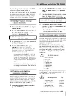
12.1Setting Program Change
receive channels
1
Press and hold down the
SHIFT
key and press
the
OPTION
key.
2
Turn the
DATA ENTRY
knob until the bottom
line of the display shows
MIDI Ch
Select
, and press
ENTER
:
3
Set the value to
defeat
, or a MIDI chan-
nel from
1
through
16
.
4
Push the
DATA ENTRY
knob to cycle
through:
Mixer
,
Effect1
,
Effect2
,
Ch Dynamics1
,
Ch
Dynamics2
,
Ch Dynamics3
and
Ch Dynamics4
.
For components other then the
Mixer
, the
MIDI channel is used for Control Change and
Program Change messages. The channels set for
the
Mixer
component refer only to Program
Change messages, not to Control Change mes-
sages.
Note that there is no Omni setting—a component
may respond to messages on one channel only or
none at all.
12.2Enabling and disabling
parameter changes
Parameter changes of the TM-D1000 can be trans-
mitted over MIDI from a sequencer or sequencing
program, and used to control the settings. These
parameter changes may be disabled when either the
REC and/or the MIX user mode is selected:
1
Press and hold down the
ENTER
key, and
press the
OPTION
key.
2
Turn the
DATA ENTRY
knob until the bottom
line of the display shows
MIDI
, and press
ENTER
.
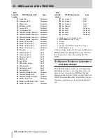
3
Turn the
DATA ENTRY
knob until the bottom
line of the display shows
Control
Change Defeat
, and press
ENTER
:
4
Use the
DATA ENTRY
knob to change
between
Yes
and
No
. Press
ENTER
to con-
firm your selection.
Remember that a setting of
Yes
means that the
Control Change is disabled for this mode.
12.3Recording parameter changes
Parameter changes may be recorded in real time from
mix moves on the TM-D1000, or produced from any
other MIDI controller, and edited before being
replayed by a sequencer.
The MIDI channels used for Control Change mes-
sages are different from those used for Program
Change messages. Input channels 1 through 16 use
MIDI channels 1 through 16 respectively. In addi-
tion, channels 9 through 16 “double up” in the fol-
lowing way:
A brief summary of the controller numbers assigned
to each channel is given here (more details are avail-
able in the Reference Manual):
M I D I
C h
S e l e c t
Ã
M i x e r
C h :
1 ?
C o n t r o l
C h a n g e
D e f e a t
R E C
M o d e : Y e s ?
MIDI
channel
TM-D1000 component
9
SOLO mode control
10
Effect return
11
Aux return
12
GRP/AUX1 fader
13
GRP/AUX2 fader
14
GRP/AUX3 fader
15
GRP/AUX4 fader
16
L-R fader
MIDI
controller
number
TM-D1000 parameter
Type
7
Input channel fader
Continuous
9
L-R/Grp–AUX fader
a
Continuous
10
Pan
Continuous
11
Input channel mute
On/off
12
Effect/Aux return level
b
Continuous