background image

13

#

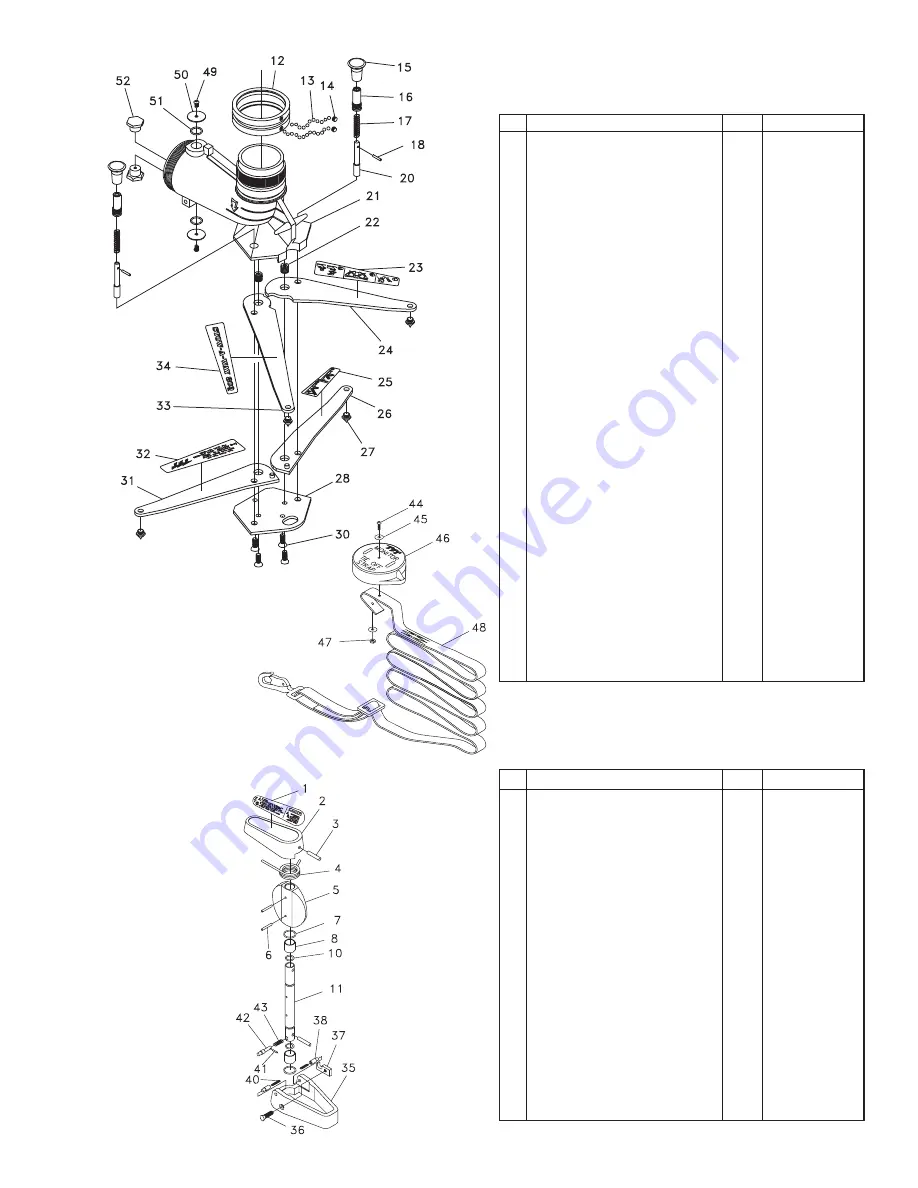
DESCRIPTION

QTY

PART #

1

2

3

4

5

6

7

8

10

11

35

36

37

38

40

41

42

43

SAFETY VALVE HANDLE LABEL

1

XL070

VALVE HANDLE

1

X540

1/4 x 1 3/8 SPIROL PIN

1

VP250X1.375H

TORSION SPRING

1

X560

BUTTERFLY

1

X550

5/32 x 1 1/8 SPIROL PIN

3

V1920

O-RING-118

2

VO-118

BUSHING

2

X565

O-RING-113

2

VO-113

VALVE SHAFT

1

X570

PADDLE

1

X530

1/4-20 x 7/8 FLAT HEAD

1

VT25E20FH875

WEAR PLATE

1

X585

PADDLE PIVOT

2

X590

PADDLE PIVOT SPRING

2

X575

3/32 x 1/2 SPIROL PIN

1

VP094X500H

TRIP PIN

1

X580

TRIP PIN SPRING

1

X582

STOW-A-WAY 800

®

without Safety Valve

#

DESCRIPTION

QTY

PART #

12

13

14

15

16

17

18

20

21

22

23

24

25

26

27

28

30

31

32

33

34

44

45

46

47

48

49

50

51

52

SWIVEL RING

1

X425

5/16 SS BALLS

76

VB.312

SWIVEL SCREW

2

X405

SHOT PIN KNOB

2

X430

KNOB BARREL

2

X440

SHOT PIN SPRING

2

X445

5/32 x 7/8 SPIROL PIN

2

V1900

SHOT PIN

2

X435

BASE

1

X420

BELLEVILLE WASHER

12

D07590

INSTRUCTION LEG LABEL 1-3

1

XL010

FRONT LEG - LEFT

1

X470L

INSTRUCTION LEG LABEL 4-5

1

XL020

REAR LEG - LEFT

1

X460L

SPIKE

4

X480

BOTTOM PLATE

1

X450

3/8-16 X 3/4 FLAT HEAD SHCS

4

VT37-16FH750

REAR LEG - RIGHT

1

X460R

TFT LEG LABEL

1

XL050

FRONT LEG - RIGHT

1

X470R

SAFE-TAK LEG LABEL

1

XL040

#10-32 x 3/4 BUTTON HEAD

1

VT10E32BH750

STAINLESS STEEL WASHER 18-8

2

V2038

STRAP CAP

1

X457

#10-32 HEX NUT

1

VT10-32NT

STRAP ASSEMBLY

1

RX455

1/4-28 X ½ BUTTONHEAD

2

VT25-28BH500

2.5" CLAPPER WASHER

2

X752

O-RING-118

2

VO-118

PLUG

2

X510

XF500-KIT

VALVE UPGRADE KIT

See

Section

5.6

Summary of Contents for CROSSFIRE

Page 1: ...ing and Emergency Response are inherently dangerous activities requiring proper training in their hazards and the use of extreme caution at all times 2 It is your responsibility to read and understand...

Page 2: ...with a particular hazard Per ANSI standard Z535 4 1998 the definitions of the three signal words are as follows DANGER CAUTION WARNING DANGER indicates an imminently hazardous situation which if not...

Page 3: ...the line or equipment Distance from the nozzle to the line or equipment Size of the stream Whether the stream is solid or broken Purity of the water 2 WARNING 1 2 Electrostatic Hazards of Foam Blanket...

Page 4: ...ontrols Figure 3 1 3 Figure 3 1 2 Figure 3 1 1 CROSSFIRE MONITOR TOP STOW A WAY 800 BASE TRUCK MOUNT ADAPTOR COMPANION FLANGE Carrying Handle Inlet Pressure Gauge Elevation Pin Stop Anchor Strap Stora...

Page 5: ...its down position as shown in Figures 4 4 1 4 4 2 Before the monitor is removed from the base the rotation lock should be manually disengaged A small spring holds the rotational lock in the unlocked p...

Page 6: ...n a portable base below this safety stop is DANGEROUS Do not operate on portable base below safety stop Injury or death can occur if the monitor and base slides or lifts off the ground Figure 4 4 1 Un...

Page 7: ...ation instructions are shipped with this accessory The storage bracket TFT part XF B for the base unit IS NOT STRONG ENOUGH to withstand the forces encountered with an operating monitor and is not int...

Page 8: ...hould be a safe distance from the fire yet within reach of the nozzle stream Select a flat even surface within 8 feet of a sturdy stationary object that can be used as an attachment point for the anch...

Page 9: ...strap in the base and protect the sealing surface of the quick connect swivel joint Whenever the monitor is operated on the portable base the base must be anchored to a substantial immovable object A...

Page 10: ...to the label on the bottom side of the pressure relief valve A pressure relief valve can be added to the single inlet portable base by removing the cover on the side of the base For additional inform...

Page 11: ...gear housing until excess appears 6 2 PERFORMANCE TESTS 7 0 SPECIFICATIONS CROSSFIRE Monitor STOW A WAY 800 Base Weight Storage Volume L W H Height Above Truck Flange Height Above Truck Deck min Heig...

Page 12: ...AINTENANCE Read instruction manual before use Operation of this device without understanding the manual and receiving proper training is a misuse of this equipment A person who has not read and unders...

Page 13: ...2 33 34 44 45 46 47 48 49 50 51 52 SWIVEL RING 1 X425 5 16 SS BALLS 76 VB 312 SWIVEL SCREW 2 X405 SHOT PIN KNOB 2 X430 KNOB BARREL 2 X440 SHOT PIN SPRING 2 X445 5 32 x 7 8 SPIROL PIN 2 V1900 SHOT PIN...

Page 14: ...Z LOCK 9991067 MIDSTATE 210049 1 A4230 27 COUPLING HEAD STROZ 5 X 5 25 PSF HARDCOAT 1 A4135 31 GASKET 5 PRESSURE MOLDED 9991000 1 A4220 32 BALL 7 16 STAINLESS 302 GRADE 100 1 VB 437 33 MATE PSM4 25 X...

Page 15: ...ended beneficiary of the equipment shall not be entitled to recover from TFT any consequential or incidental damages for injury to person and or property resulting from any defective equipment manufac...

Page 16: ...y tied down with no slack in anchor strap Flow Limited to 800 gpm 3000 l min Master nozzle pumped to 800 gpm or Stacked Tips Limited to PORTABLE BASE GENERAL WARNING 1 3 8 dia 175 PSI 1 1 2 dia 140 PS...

Reviews: