background image

©Copyright Task Force Tips, Inc. 2002 - 2015 

LIN-035 June 16, 2015 Rev15

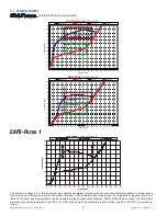
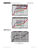
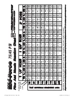
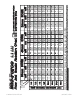
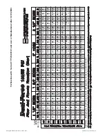
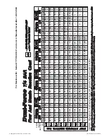
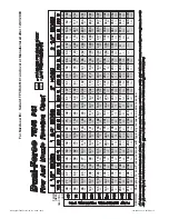
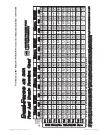
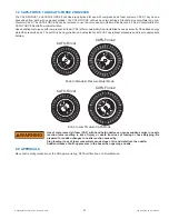
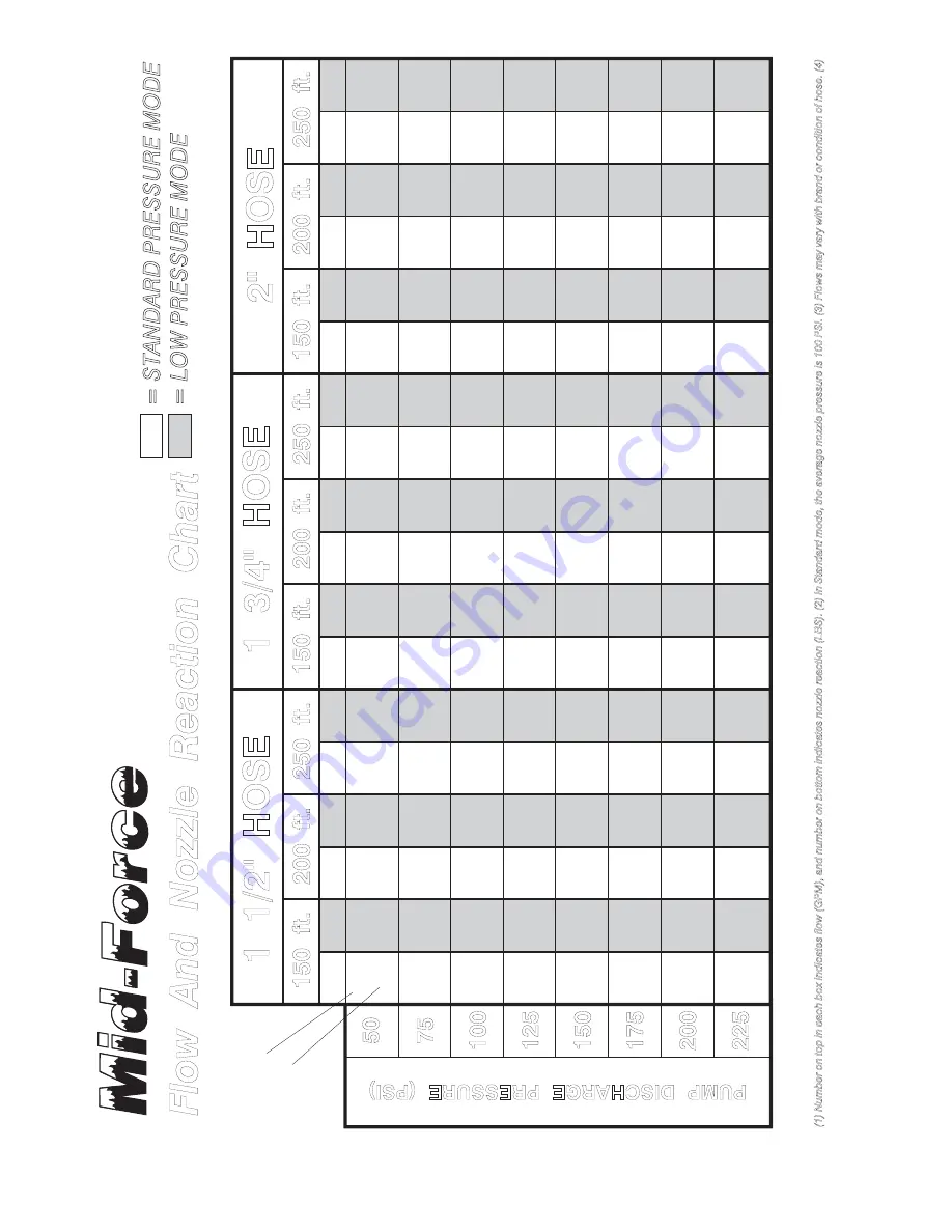
Flow And Nozzle Reaction Chart

C

A

U

T

IO

N

:  C

h

a

n

g

in

g

 t

o

 L

o

w

 P

re

ss

u

re

 m

o

d

wil

l typica

lly

 increa

se

 nozzle

 reaction.

150 ft.

150 ft.

150 ft.

200 ft.

200 ft.

200 ft.

250 ft.

250 ft.

50

225

200

175

150

125

100

75

PUMP DISCHARGE PRESSURE (PSI)

1 1/2" HOSE

1 3/4" HOSE

2" HOSE

STD

S

TD

STD

S

TD

STD

S

TD

STD

S

TD

STD

LP

LP

LP

LP

LP

LP

LP

LP

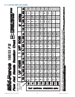
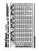
(1) Number on top in 

each box indicates flow (GPM), and numb

er on bottom indicates nozzle reaction (LB

S). (2) 

In Standard 

mode,

 the average nozzle pressure is 100 PSI. (3) Flows 

may

 v

ary with brand 

or condition of hose. (4) 

FL

OW (GPM)

REACTION (LB

S

)

= S

TA

N

D

A

R

D

 P

R

E

S

S

U

R

E M

O

D

E

= L

O

W P

R

E

S

S

U

R

E M

O

D

E

STD

LP

75/45 PSI

250 ft.

43

55

78

108

136

162

183

204

14

22

35

50

63

73

82

90

69

104

127

149

166

180

192

204

20

32

42

50

60

70

79

89

43

53

72

96

119

138

157

174

14

21

32

43

54

64

72

79

62

92

113

131

148

163

174

184

18

27

35

43

50

57

65

73

42

51

68

86

106

124

140

155

16

24

31

38

44

50

55

62

13

20

29

39

49

57

64

71

45

59

91

134

173

206

220

---

84

121

153

174

191

206

220

---

15

24

41

62

78

91

104

---

25

39

52

65

78

91

104

---

44

57

82

118

148

175

201

214

74

110

136

159

174

189

202

214

15

23

37

54

68

79

88

98

21

34

45

55

66

77

87

98

43

55

77

105

132

155

176

196

67

101

123

145

162

175

188

199

14

22

34

48

60

71

80

86

19

30

40

48

57

66

76

85

45

64

122

203

ó

ó

ó

ó

84

155

182

204

ó

ó

ó

---

97

140

171

192

210

ó

ó

ó

45

62

105

166

210

ó

ó

ó

45

60

97

146

189

215

ó

ó

25

53

71

89

ó

ó

ó

---

15

27

56

89

ó

ó

ó

---

29

47

63

79

95

ó

ó

---

16

26

48

75

95

ó

ó

---

15

25

44

67

85

99

ó

---

57

83

103

119

134

147

160

170

LP

89

128

162

181

199

214

ó

ó

26

42

56

70

85

99

ó

---

Summary of Contents for Dual-Force

Page 1: ... the use of extreme caution at all times 2 It is your responsibility to read and understand any user s instructions including purpose and limitations provided with any piece of equipment you may be called upon to use 3 It is your responsibility to know that you have been properly trained in Firefighting and or Emergency Response and in the use precautions and care of any equipment you may be calle...

Page 2: ...HLOW CONTROL 5 1 5 1 IMPULSE TRIGGER LOCK 5 1 5 2 TRIGGER FLOW CONTROL SPEED ADJUSTMENT 5 2 PATTERN CONTROL ADJUSTMENT 5 2 1 PATTERN CONTROL 5 2 2 FLUSH CONTROL 5 3 STANDARD LOW PRESSURE KNOB MID FORCE DUAL FORCE 6 0 USE WITH FOAM 6 1 FOAM ASPIRATING ATTACHMENTS 7 0 USE OF NOZZLES 7 1 MID FORCE AND DUAL FORCE NOZZLES 7 2 CAFS FORCE 1 AND CAFS FORCE 2 NOZZLES 8 0 APPROVALS 9 0 COLOR CODED VALVE HAN...

Page 3: ...y as supply conditions change such as opening or closing other nozzles hose line kinks changes in pump settings etc Changes in spray pattern or flushing will also affect nozzle reaction The nozzle operator must always be prepared in the event of these changes WARNING If nozzle gets out of control or away from operator retreat from nozzle immediately Do not attempt to regain control of nozzle while...

Page 4: ...360 1150 75 5 1 1 2 NH CAFS FORCE1 70 200 265 760 75 5 1 1 2 NH CAFS FORCE2 95 250 360 950 75 5 1 1 2 NH Other threads coupling sizes or connector styles can be specified at time of order COUPLING RUBBER GASKET PISTOL GRIP STREAM SHAPER NOZZLE WITH VALVE nd INTEGRAL PISTOL GRIP a FLOW CONTROL ON OFF TIP ONLY NOZZLE BARREL LABEL NAME LABEL PRESSURE CONTROL KNOB VALVE HANDLE NOZZLE WITH VALVE GASKET...

Page 5: ...thread engagement over time Per NFPA 1962 if dissimilar metals are left coupled together an anti corrosive lubricant should be applied to the threads Also the coupling should be disconnected and inspected at least quarterly 3 4 USE WITH SALT WATER Use with saltwater is permissible provided nozzle is thoroughly cleaned with fresh water after each use The service life of the nozzle may be shortened ...

Page 6: ... PSI 70 GPM STANDARD PRESSURE MODE 70 200 GPM 265 760 L min FLOW RANGE LOW PRESSURE MODE CAFS Force 1 CAFS FORCE 1 75 45 PSI 5 3 BAR 0 10 20 30 40 50 60 70 80 90 100 0 20 40 60 80 100 120 140 160 180 200 220 240 260 280 300 320 FLOW GPM WATER MODE CAF MODE NFPA 75 PSI PRESSURE PSI CAF MODE WATER MODE 90 PSI 60 PSI 75 GPM 200 GPM The charts in section 4 2 of this document give specific examples of ...

Page 7: ...ODE 95 225 GPM 360 850 L min FLOW RANGE 90 PSI 250 GPM 60 PSI 225 GPM 30 PSI 0 10 20 30 40 50 60 70 80 90 100 110 120 0 20 40 60 80 100 120 140 160 180 200 220 240 260 280 300 320 Pressure PSI Flow GPM New DUAL FORCE 75 45 PSI 5 3 BAR meets NFPA For Nozzles Manufactured after December 1 2003 STANDRAD 75PSI LOW 45PSI NFPA 75 PSI NFPA 45 PSI 95 GPM STANDARD PRESSURE MODE 95 250 GPM 360 950 L min FLO...

Page 8: ... 67 97 125 151 175 198 8 14 32 48 63 78 91 102 60 100 129 152 174 192 207 221 19 33 45 56 66 76 86 96 21 31 63 91 114 136 157 176 7 13 29 44 57 70 81 91 54 91 117 138 158 175 189 203 17 30 40 50 58 66 75 83 22 36 84 135 196 8 15 41 69 101 82 141 184 213 27 51 72 90 22 35 79 122 168 212 8 15 38 62 87 109 75 128 167 198 220 24 45 63 79 95 113 151 187 222 113 PUMP DISCHARGE PRESSURE PSI 1 1 2 HOSE 1 ...

Page 9: ... 4 6 15 22 29 35 41 46 225 380 490 575 660 725 785 835 9 15 20 25 30 35 39 44 80 115 240 345 430 515 595 665 3 6 13 20 26 32 37 41 205 345 445 520 600 660 715 770 8 14 18 23 26 30 34 38 85 135 320 510 740 4 175 19 31 46 310 535 695 805 12 23 33 41 85 130 300 460 635 800 4 7 17 28 40 50 285 485 630 750 11 20 29 36 85 130 285 430 570 710 840 4 7 16 26 35 44 51 38mm HOSE 45mm HOSE 50mm HOSE 7 bar LP ...

Page 10: ... 108 136 162 183 204 14 22 35 50 63 73 82 90 69 104 127 149 166 180 192 204 20 32 42 50 60 70 79 89 43 53 72 96 119 138 157 174 14 21 32 43 54 64 72 79 62 92 113 131 148 163 174 184 18 27 35 43 50 57 65 73 42 51 68 86 106 124 140 155 16 24 31 38 44 50 55 62 13 20 29 39 49 57 64 71 45 59 91 134 173 206 220 84 121 153 174 191 206 220 15 24 41 62 78 91 104 25 39 52 65 78 91 104 44 57 82 118 148 175 2...

Page 11: ...SSURE BAR LP 261 394 481 564 628 681 727 772 163 208 295 409 515 613 693 772 6 10 16 23 29 33 37 41 9 15 19 23 27 32 36 40 163 201 273 363 450 522 594 659 235 348 428 496 560 617 659 696 8 12 16 20 23 26 29 33 6 10 15 20 24 29 33 36 216 314 390 450 507 556 606 643 159 193 257 326 401 469 530 587 7 11 14 17 20 23 25 28 6 9 13 18 22 26 29 32 318 458 579 659 723 780 833 170 223 344 507 655 780 833 11...

Page 12: ...36 44 51 58 64 71 77 14 21 28 38 47 56 64 71 81 15 23 33 46 59 71 81 91 100 50 61 83 119 151 179 204 227 248 62 110 144 172 196 217 237 255 269 49 60 77 107 134 158 179 199 216 56 98 128 152 174 193 210 226 241 48 59 73 98 122 143 162 179 195 50 61 86 126 160 190 217 242 264 17 25 38 58 75 91 105 117 129 14 24 32 39 45 51 57 62 67 20 38 52 65 77 88 99 110 122 16 24 35 51 66 79 91 101 112 18 33 45 ...

Page 13: ...35 6 10 13 17 21 25 29 32 35 7 10 15 21 27 32 37 41 45 189 231 314 450 572 678 772 859 939 235 416 545 651 742 821 897 965 1018 185 227 291 405 507 598 678 753 818 212 371 484 575 659 731 795 855 912 182 223 276 371 462 541 613 678 738 189 231 326 477 606 719 821 916 999 8 11 17 26 34 41 48 53 59 6 11 15 18 20 23 26 28 30 9 17 24 29 35 40 45 50 55 7 11 16 23 30 36 41 46 51 8 15 20 25 30 34 38 42 4...

Page 14: ...9 87 94 50 73 115 149 177 203 227 249 269 84 126 157 183 206 225 241 257 271 49 67 103 131 156 178 198 216 234 75 112 139 162 182 201 217 231 244 48 63 93 119 141 160 178 195 210 50 76 121 158 189 217 243 266 284 17 29 48 64 78 91 102 113 123 16 24 31 37 43 48 53 58 63 25 39 52 63 74 86 98 109 122 16 26 42 56 68 79 88 97 106 22 34 44 54 63 71 80 90 99 17 31 51 69 84 98 110 121 133 70 101 126 147 1...

Page 15: ...32 36 39 43 189 276 435 564 670 768 859 942 1018 318 477 594 693 780 852 912 973 1026 185 254 390 496 590 674 749 818 886 284 424 526 613 689 761 821 874 924 182 238 352 450 534 606 674 738 795 189 288 458 598 715 821 920 1007 1075 8 13 22 29 35 41 46 51 56 7 11 14 17 20 22 24 26 29 11 18 24 29 34 39 44 49 55 7 12 19 25 31 36 40 44 48 10 15 20 24 29 32 36 41 45 8 14 23 31 38 44 50 55 60 265 382 47...

Page 16: ...n flows different than those shown For situations or lengths of hose not listed on the chart approximate flows can be calculated using conventional hydraulics All reach testing was taken in still air conditions at an elevation of 30 degrees MID FORCE Flow range 70 200 GPM automatic pressure control at emergency low pressure mode NOZZLE TESTED Mid Force Model HM VPGI Serial TFTH 145249 MODEL HD VPG...

Page 17: ...with Tip Only nozzles is shut off when the valve handle is fully forward Pulling back on the handle opens the valve Open valve slowly to avoid sudden changes in nozzle reaction Close valve slowly to prevent water hammer Note In partially open positions a ball valve will cause turbulence and adversely affect stream quality Nozzles attached to an in service hose shall be stored in the off position 5...

Page 18: ...de fog Turning the stream shaper clockwise as seen from the operating position behind the nozzle moves the shaper to the straight stream position Turning the shaper counterclockwise will result in an increasingly wider pattern Since the stream trim point varies with flow the stream should be trimmed after changing the flow to obtain the straightest and farthest reaching stream To properly trim the...

Page 19: ...rations WARNING Large amounts or pieces of debris may be unflushable and can reduce the flow of the nozzle resulting in an ineffective flow In the event of a blockage it may be necessary to retreat to a safe area uncouple the nozzle and remove debris 5 3 STANDARD LOW PRESSURE KNOB MID FORCE DUAL FORCE For situations where the standard pressure setting at the nozzle is impractical the MID FORCE or ...

Page 20: ...jury or death from loss of footing or hose whipping Be prepared for sudden changes in nozzle reaction caused by Slug loading Loss of foam concentrate sends slugs of air and water into the nozzle Sudden release of built up pressure in the hose when opening a nozzle 6 1 FOAM ASPIRATING ATTACHMENTS Multi expansion or low expansion aspirating attachments may be used with nozzles to increase the expans...

Page 21: ...hoses as a result of the added energy stored by pressurized air The authority having jurisdiction must establish safe CAF operational procedures and insure appropriate training Knob In Low Pressure CAFS Mode Knob In Standard Pressure Water Mode CAFS Force1 CAFS Force2 CAFS Force1 CAFS Force2 WARNING Use of compressed air foam CAF with hand held nozzles can cause sudden surges in nozzle reaction fo...

Page 22: ... 6 Preconnect or discharge 7 Foam Lines Orange Red Yellow White Blue Black Green Red w White border Red White Other Colors Available Gray Pink Purple Tan 9 1 IMPULSE TRIGGER VALVE SYSTEM NOZZLE COLORED PISTOL GRIPS The TFT Impulse Trigger Valve System nozzles are supplied with black pistol grip covers The pistol grip covers are available from TFT in various colors for those departments wishing to ...

Page 23: ... discharge of its obligations under this limited warranty If TFT makes this election claimant shall return the equipment to TFT free and clear of any liens and encumbrances This is a limited warranty The original purchaser of the equipment any person to whom it is transferred and any person who is an intended or unintended beneficiary of the equipment shall not be entitled to recover from TFT any ...

Page 24: ... the pattern to STRAIGHT STREAM Then spray a short burst into these areas 1 FRONT PATTERN CONTROL SEAL Spray in between the pattern control and the barrel 2 PRESSURE CONTROL UNIT Place check sticks behind baffle while shaper is in flush Cycle baffle in and out using check sticks several times to work lubrication into o rings 3 FRONT SLIDER SEAL a Rotate shaper into FLUSH position b Spray down the ...

Page 25: ...p keep excess BreakFree from the outside of the nozzle 3 Keep nozzle upside down for at least 10 seconds to allow the BreakFree to flow into the valve area 4 Check for smooth and free operation of the trigger Repeat a second time if needed Holding a rag around the tube here can help keep excess BreakFree from the outside of the nozzle If this procedure does not restore trigger operation then facto...

Page 26: ... pressure 2 percent 3 The valve or shut off and pattern controls shall be operated through their full range of motion at 100 psi 6 9 bar or 690 kPa with no signs of leaking binding or other problems 4 Evaluate the flow of nozzles as defined by NFPA 1964 in the following manner Automatic Constant Pressure Spray Nozzles 1 The flow rate shall slowly be increased to the maximum rated flow and the mini...

Page 27: ...to equipment or injury to personnel that is a result of user service Contact the factory or visit the web site at www tft com for parts lists exploded views test procedures and troubleshooting guides Performance tests shall be conducted on the nozzle after a repair or anytime a problem is reported to verify operation in accordance with TFT test procedures Consult factory for the procedure that cor...

Page 28: ...tes smoothly and positively BEFORE BEING PLACED BACK IN SERVICE nozzles must be inspected to this checklist 1 All controls and adjustments are operational 2 Shut off valve if so equipped closes off the flow completely 3 There are no broken or missing parts 4 There is no damage to the nozzle that could impair safe operation e g dents cracks corrosion or other defects 5 The thread gasket is in good ...

Reviews: