
©Copyright Task Force Tips, Inc. 2002 - 2015
LIN-035 June 16, 2015 Rev15
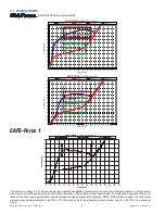
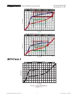
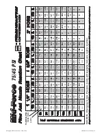
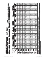
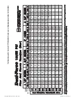
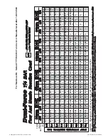
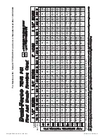
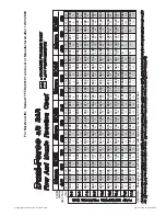
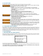
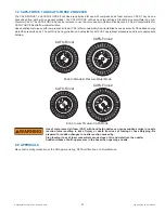
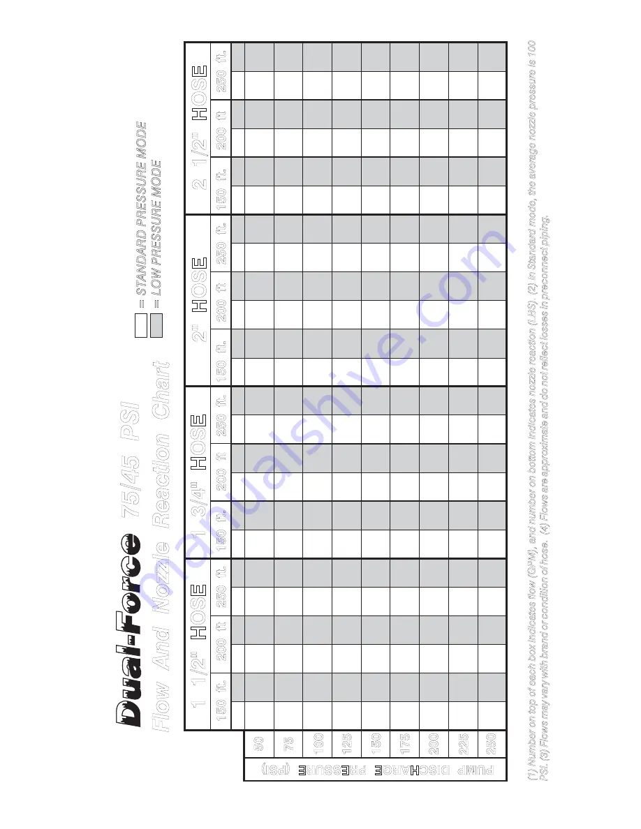
Flow And Nozzle Reaction Chart
150 ft.
150 ft.
150 ft.
200 ft
200 ft
200 ft
250 ft.
250 ft.
250 ft.
1 1/2" HOSE
1 3/4" HOSE
2" HOSE
50
250
225
200
175
150
125
100
75
PUMP DISCHARGE PRES
SURE (PSI)
16
25
39
52
63
72
81
89
97
STD
S
TD
STD
S
TD
STD
S
TD
STD
S
TD
STD
LP
LP
LP
LP
LP
LP
LP
LP
LP
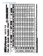
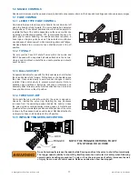
CA
UTION:
Chan
ging
to
Low
Pressu
re
mod
e will
typ
ical
ly
in
crease
no
zz
le
r
e
actio
n
.
(1) Number
on top of each box
indicates
flow
(GPM),
and number
on bottom
indicates
nozzle
reaction
(LB
S).
(2) In Standard
mode,
the
average nozzle pressure
is
100
PSI.
(3)
Flows
may
vary
with
brand
or condition
of hose.
(4) Flows
are approximate
and do not
reflect
losses
in
preconnect
pip
ing.
FL
OW
(GPM)
REACTION
(LB
S
)
=
ST
AN
DAR
D
PRES
SURE
M
O
DE
=
L
O
W
PR
ES
SUR
E MODE
STD
LP
48
64
96
122
145
165
183
200
216
71
104
130
151
170
187
202
216
229
47
60
85
108
124
144
160
174
188
65
91
114
133
149
164
178
190
202
45
58
77
98
115
130
144
157
169
60
82
103
120
135
148
160
172
182
20
31
41
49
57
65
72
80
88
15
23
34
45
54
62
70
77
83
18
27
35
42
48
55
61
66
72
14
22
31
40
48
56
62
68
74
15
25
38
50
61
70
79
87
94
50
73
115
149
177
203
227
249
269
84
126
157
183
206
225
241
257
271
49
67
103
131
156
178
198
216
234
75
112
139
162
182
201
217
231
244
48
63
93
119
141
160
178
195
210
50
76
121
158
189
217
243
266
284
17
29
48
64
78
91
102
113
123
16
24
31
37
43
48
53
58
63
25
39
52
63
74
86
98
109
122
16
26
42
56
68
79
88
97
106
22
34
44
54
63
71
80
90
99
17
31
51
69
84
98
110
121
133
70
101
126
147
165
182
197
211
223
51
88
148
197
239
276
295
312
329
107
162
203
232
256
276
295
313
336
51
81
132
173
210
242
270
289
304
96
145
182
212
234
255
272
288
304
88
133
166
194
218
236
254
269
284
20
30
39
48
55
63
70
77
85
18
36
64
88
108
127
145
163
181
33
54
72
90
108
127
145
163
180
17
33
57
76
94
109
123
138
154
29
47
63
77
92
108
123
138
154
26
42
56
68
81
94
107
120
134
150 ft.
200 ft
250 ft.
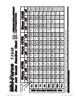
2 1/2" HOSE
STD
S
TD
STD
LP
LP
LP
53
111
206
282
307
343
356
368
380
18
46
92
131
157
186
210
232
255
53
123
252
300
343
356
369
ó
---
157
230
269
300
341
355
368
ó
---
53
116
224
290
317
349
362
375
ó
148
221
260
290
335
348
361
373
ó
140
212
251
281
307
342
354
367
378
19
52
114
150
185
210
235
ó
---
52
89
120
150
185
209
234
ó
---
19
49
101
140
167
198
222
245
---
48
83
112
140
173
197
221
245
---
45
77
105
131
157
186
209
232
255
75/45 PSI
Fo
r Nozzles with: Serial # TF
T-
H465101 and over or Manufactured after 12/01/2003


