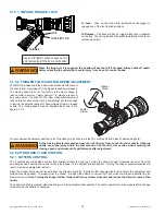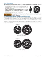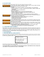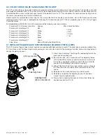
©Copyright Task Force Tips, Inc. 2002 - 2015
LIN-035 June 16, 2015 Rev15
16
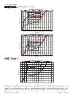
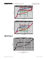
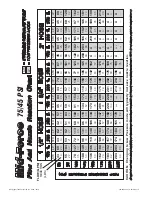
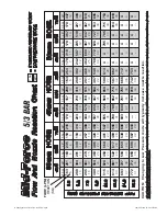
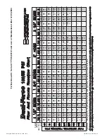
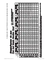
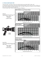
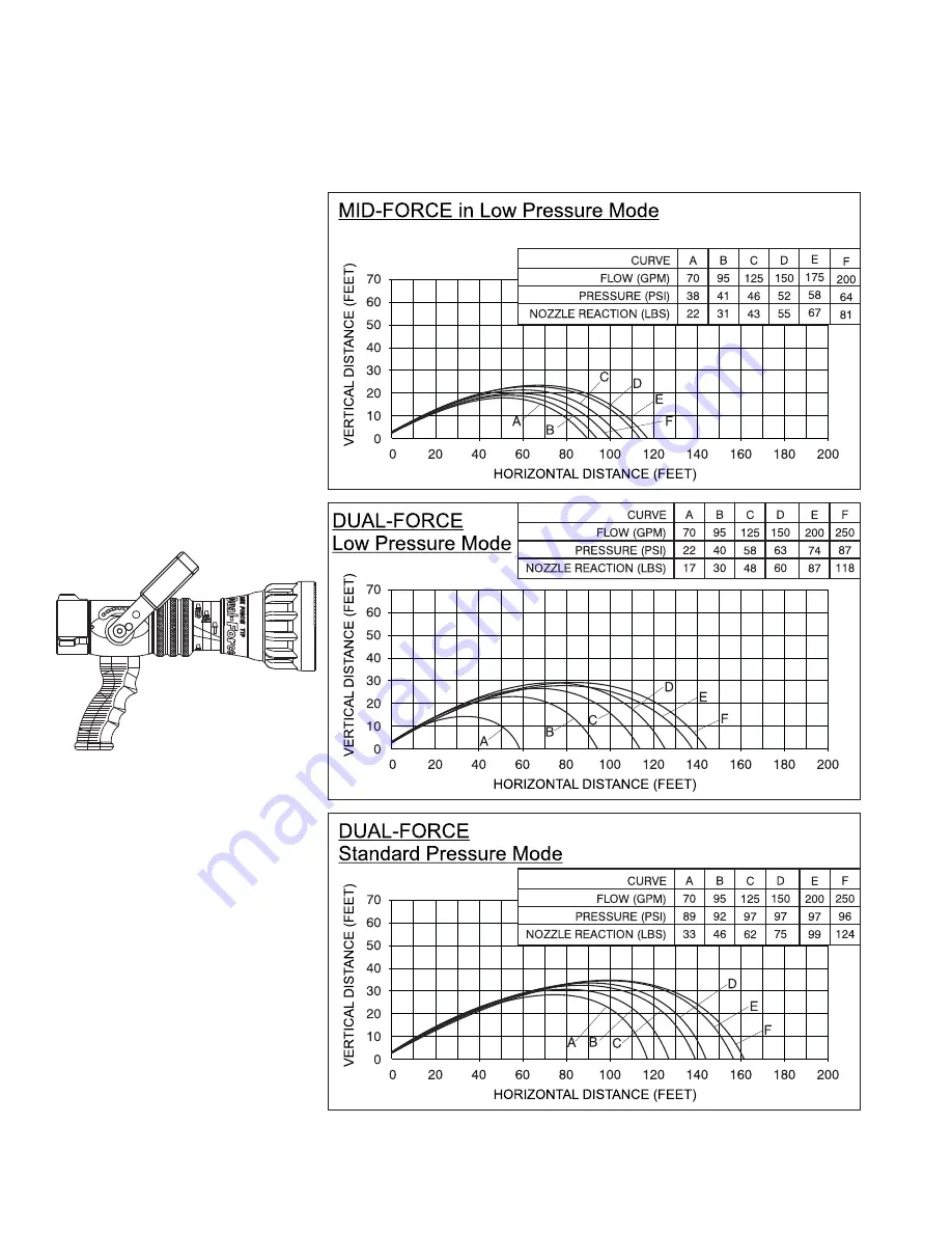
4.3 REACH AND TRAJECTORY
Care must be taken to avoid dents or nicks in the nozzle tip because they can seriously affect the stream reach.
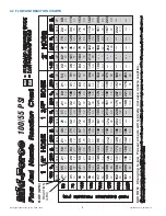
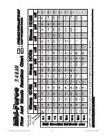
The following are specifi c examples of maximum fl ow rates for particular situations. Friction losses may vary due to differences in
hose construction resulting in fl ows different than those shown. For situations or lengths of hose not listed on the chart, approximate
fl ows can be calculated using conventional hydraulics.
All reach testing was taken in still air conditions at an elevation of 30 degrees.
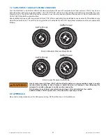
MID-FORCE
Flow range 70-200 GPM, automatic pressure
control at emergency low pressure mode.
NOZZLE TESTED
Mid-Force
Model: HM-VPGI
Serial #: TFTH-145249
MODEL
HD-VPGI
SHOWN
DUAL-FORCE
Flow range 70-250 GPM, automatic pressure
control with 100 PSI and emergency low
pressure mode.
NOZZLE TESTED
DUAL-FORCE
Model: HD-VPGI
Serial #: TFTH-041501

