background image

©Copyright Task Force Tips LLC  2011-2018 

LIG-010 May 29, 2018 Rev05

13

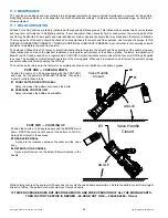
5.2.4  FLUSH CONTROL

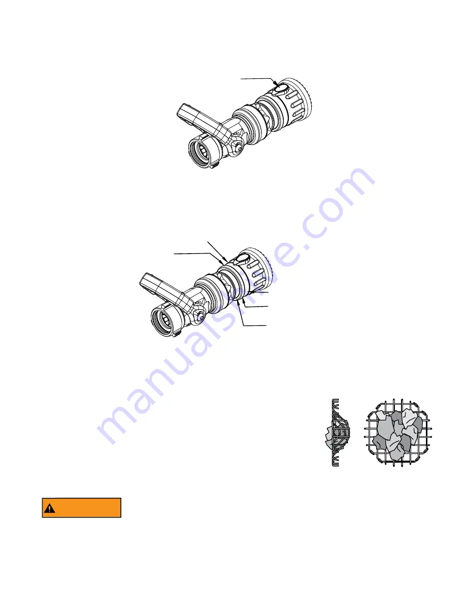
Small debris passes through the debris screen (if equipped) and may get caught inside the 

nozzle. This trapped material will cause poor stream quality, shortened reach, and reduced 

flow. To remove small debris, the nozzle may be flushed as follows:

• While still flowing water, rotate the shaper counterclockwise (as viewed from behind 

the nozzle) to the flush position. (increased resistance will be felt on the SHAPER or 

RING as the nozzle goes into flush) This will open the nozzle allowing debris to pass 

through.
•  During  flush  the  nozzle  reaction  will  decrease  as  the  pattern  becomes  wider  and 

the pressure drops. The nozzle operator must be prepared for an increase of nozzle 

reaction when returning the nozzle from the flush position to retain control of the nozzle.
• Rotate the selector ring out of flush to continue normal operations.

WARNING

Large amounts or pieces of debris may be unflushable and can reduce the flow of the nozzle 

resulting in an ineffective flow. In the event of a blockage, it may be necessary to retreat to a 

safe area, uncouple the nozzle and remove debris.

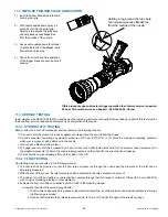
5.2.3  FOG ANGLE ADJUSTMENT

Typically the G-Force is factory set with the tactile indicator in the top position for straight stream. The fog angle can be adjusted 

while keeping the tactile indicator on top by following the steps in figure 5.2.3. You will need a new shaper label if you change the 

fog angle adjustment.

1)

 Remove or cut the shaper label.

2)

 Loosen the clamp ring 

     with a pin spanner.

3)

 While keeping the tactile indicator 

     or lock out lever on top, 

     rotate the shaper guide 

     to obtain the desired fog angle.

4)

 Tighten the clamp ring 

     with a pin spanner.

5)

 Apply a new shaper label.

Figure 5.2.3

Fog Angle Adjustment

5.2.2  SHAPER TACTILE INDICATOR

The G-Force has a tactile indicator on the stream shaper. The tactile indicator allows the stream shaper position (and fog angle) to 

be determined by feel rather than by sight. The fog angle can be adjusted (see section 5.2.3) so that a desired fog angle is achieved 

when the tactile indicator in on top of the nozzle. The G-Force has an optional detent to aid in returning to a known fog angle. Note: 

The fog angle will change as flow and pressure change (becoming wider with increased flow).

TACTILE INDICATOR

(MOVES WITH BUMPER)

Figure 5.2.2

Shaper Tactile Indicator

Summary of Contents for G-Force Series

Page 1: ...ty information at tft com serial number This Instruction Manual is intended to familiarize firefighters and maintenance personnel with the operation servicing and safety procedures associated with the G Force nozzle This manual should be kept available to all operating and maintenance personnel 3701 Innovation Way Valparaiso IN 46383 9327 USA 800 348 2686 219 462 6161 Fax 219 464 7155 G Force with...

Page 2: ...ent you may be called upon to use 3 It is your responsibility to know that you have been properly trained in Firefighting and or Emergency Response and in the use precautions and care of any equipment you may be called upon to use 4 It is your responsibility to be in proper physical condition and to maintain the personal skill level required to operate any equipment you may be called upon to use 5...

Page 3: ...USTMENT 5 1 4 3 NORMAL OPERATING POSITION 5 2 PATTERN AND FLUSH CONTROL 5 2 1 PATTERN CONTROL 5 2 2 SHAPER TACTILE INDICATOR 5 2 3 FOG ANGLE ADJUSTMENT 5 2 4 FLUSH CONTROL 6 0 USE WITH FOAM 6 1 FOAM ASPIRATING ATTACHMENTS 7 0 USE OF G FORCE NOZZLES 8 0 APPROVALS 9 0 COLOR CODED VALVE HANDLE AND PISTOL GRIP 9 1 IMPULSE TRIGGER VALVE SYSTEM NOZZLE COLORED PISTOL GRIPS 10 0 DRAWINGS AND PART LISTS 10...

Page 4: ...ed by qualified personnel before being considered safe for use WARNING This equipment is intended for use by trained personnel for firefighting Their use for other purposes may involve hazards not addressed by this manual Seek appropriate guidance and training to reduce risk of injury WARNING Failure to restrain nozzle reaction can cause firefighter injury from loss of footing and or stream protec...

Page 5: ...tions are Fixed flow see section 4 1 Selectable flow see section 4 2 Automatic see section 4 3 3 0 GENERAL INFORMATION The Task Force Tips G Force nozzles are designed to provide excellent performance under most fire fighting conditions Their rugged construction is compatible with the use of fresh water see section 3 4 for saltwater use as well as fire fighting foam solutions Two body sizes are av...

Page 6: ... POSITION LOCK NOZZLE WITH IMPULSE TRIGGER VALVE SYSTEM TACTILE INDICATOR STREAM SHAPER Figure 3 1B Other options are Fixed rubber fixed aluminum or stainless steel spinning fog teeth Shaper tactile indicator with or without detent see section 5 2 2 Three flow options are available All three use the selector ring for flush control The flow options are Fixed flow see section 4 1 Selectable flow see...

Page 7: ...t off 370 psi 25 5 bar 370 psi 25 5 bar 580 psi 40 0 bar Operating temperature range of fluid 33 to 120º F 1 to 50º C Storage temperature range 40 to 150º F 40 to 65º C Materials used Aluminum 6000 series hard anodized MIL8625 class 3 type 2 stainless steel 300 series nylon 6 6 nitrile rubber 3 3 NOZZLE COUPLINGS Many inlet couplings such as NH National Hose is standard or NPSH National Pipe Strai...

Page 8: ...60 80 100 120 140 0 20 40 60 80 100 120 140 160 Flow l min Pressure bar Pressure psi Flow gpm FLUSH A B C D E F GD A FIXED GALLONAGE SELECTABLE GALLONAGE 285 l min 700 kPa 7 bar 75 gpm 100 psi 380 l min 700 kPa 7 bar 100 gpm 100 psi 15 45 75 60 gpm 100 psi 30 E F A B C D E GD C GD F Figure 4 2C 1 5 G Force 100 psi Fixed and Selectable Nozzles 0 50 100 150 200 250 300 350 400 450 500 550 600 0 1 2 ...

Page 9: ... gpm Pressure psi 0 1 2 3 4 5 6 7 8 9 0 100 200 300 400 500 600 700 800 Flow LPM Pressure BAR AUTOMATIC FLUSH 60 150 GPM 75 PSI AUTOMATIC 230 570 l min 500 kPa 5 bar G F Figure 4 3B 1 5 G Force 75 psi Automatics 0 50 100 150 200 250 300 350 400 450 500 550 600 0 1 2 3 4 5 6 7 8 9 0 20 40 60 80 100 120 140 0 20 40 60 80 100 120 140 160 Flow l min Pressure bar Pressure psi Flow gpm GD N AUTOMATIC FL...

Page 10: ...NLY ON OFF ON OFF Tip only nozzles have NO shut off valve within the nozzle and MUST be used with a separate ball valve attached to the nozzle 5 1 3 BALL SHUT OFF A separate ball valve for use with Tip Only nozzles is shut off when the valve handle is fully forward Pulling back on the handle opens the valve Open valve slowly to avoid sudden changes in nozzle reaction Close valve slowly to prevent ...

Page 11: ...ult in the loss of dampening fluid Slower Close Faster Close Figure 5 1 4 2 WARNING As the closing time is increased so does the risk of injury from an out of control nozzle A flowing nozzle can cause injury within the first second of lost control Use caution when adjusting the closing speed and always verify performance after adjustment 5 1 4 1 IMPULSE TRIGGER LOCK Use an 1 8 3mm punch to push ou...

Page 12: ...ozzle reaction is greatest when the shaper is in the straight stream position The nozzle operator must be prepared for a change in reaction as the pattern is changed Care must be taken to avoid dents or nicks in the nozzle tip because they can seriously affect the stream reach OFF ON FLOW COUNTER CLOCKWISE OFF ON FLOW CLOCKWISE 5 1 4 3 NORMAL OPERATING POSITION 45 15 90 45 Horizontal Slow Closer O...

Page 13: ... be necessary to retreat to a safe area uncouple the nozzle and remove debris 5 2 3 FOG ANGLE ADJUSTMENT Typically the G Force is factory set with the tactile indicator in the top position for straight stream The fog angle can be adjusted while keeping the tactile indicator on top by following the steps in figure 5 2 3 You will need a new shaper label if you change the fog angle adjustment 1 Remov...

Page 14: ...ased due to the greater amount of bubbles in the stream and their ability to penetrate the air Generally the reach with foam is approximately 10 less than with water only Actual results will vary based on brand of foam hardness of water temperature etc See Foamjet instruction manual for specific information See LIA 025 MANUAL Foam Attachments for TFT Nozzles FOAMJET MODEL NUMBER 1 5 G Force MX FJ ...

Page 15: ...cation 6 Flow nozzle to check performance of slow closer Adjust as needed see section 5 1 4 2 8 0 APPROVALS Many nozzle configurations carry the FM Approval rating NFPA certification or EN certification 9 0 COLOR CODED VALVE HANDLE AND PISTOL GRIP The TFT G FORCE with lever type valve handles are supplied with black valve handle covers and pistol grips The handle covers and pistol grips are availa...

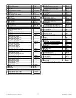
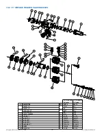
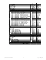
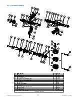
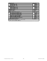
Page 16: ...8 44 42 56 56 63 64 65 66 61 62 59 60 57 56 30 8 DESCRIPTION QTY PART 1 GASKET 1 5 1 V3130 2 COUPLING 1 5 BSPF STRETCH 1 G691B COUPLING 1 5 NHF G690 SWIVEL 2 0 BSPM G693 SWIVEL 2 5 BIC MALE G694 3 COUPLING NFTS 1 5 F 1 G698 4 GASKET GRABBER 1 G606 5 O RING 134 1 VO 134 DESCRIPTION QTY PART 6 1 4 28 X 3 8 SOCKET SET SCREW 1 VT25 28SS375 7 3 16 SS BALL 34 V2120 8 O RING 032 1 VO 032 9 NFTS ADAPTER 1...

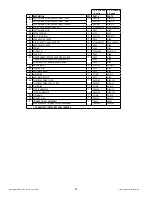
Page 17: ... PSI G641S1L INDEX RING LABEL G FORCE 150 GPM 100 PSI G641S5L INDEX RING LABEL G FORCE 150 GPM 75 PSI G641S6L 31 SUBRING 1 G640 32 INDEX RING 1 G641 suffix is engraved on raised lug 33 CLAMP RING 1 G656 34 CLAMP RING LABEL G FORCE BLUE 1 G656L B CLAMP RING LABEL G FORCE GREY G656L G CLAMP RING LABEL G FORCE BLACK G656L K DESCRIPTION QTY PART 35 SHAPER GUIDE LABEL G FORCE BLUE 1 G655L B SHAPER GUID...

Page 18: ...51 52 53 48 49 46 47 44 43 18 A 1 5 G FORCE w 1 0 valve 1 5 G FORCE w 1 5 valve DESCRIPTION QTY PART PART 1 GASKET 1 0 1 V3040 N A GASKET 1 5 N A V3130 2 COUPLING 1 0 F 1 B680 N A COUPLING 1 5 F N A G690 3 GASKET GRABBER 1 B730 G606 4 VO RING 1 VO 127 VO 134 5 LABEL TOP 1 TN600LT TN600LT 6 LABEL LEFT 1 TN600LL TN600LL 7 VALVE BODY 1 TN600G10 TN600G15 8 QUAD RING 2 VOQ 4125 VOQ 4130 9 SLIDER 1 TN66...

Page 19: ...X RING LABEL G FORCE AUTO 75 PSI 30 80 60 110 110 150 GPM G641L8L G641L8L INDEX RING LABEL G FORCE AUTO 100 PSI 60 150 GPM NO AUTO 150 I G641L9L G641L9L INDEX RING LABEL G FORCE 30 60 95 125 150GPM 100PSI G641S0L G641S0L INDEX RING LABEL G FORCE W FM 30 60 95 125 150GPM 100PSI G641S0L FM G641S0L FM INDEX RING LABEL G FORCE 30 60 95 125 150 GPM 75 PSI G641S1L G641S1L INDEX RING LABEL G FORCE 150 GP...

Page 20: ...SE 1 G658 G658 40 SPRING 1 G662 G662 41 DOWEL PIN 1 VP094X 50 VP094X 50 42 LOCK PIN 1 G660 G660 43 FIXED RUBBER TEETH SHAPER WITH BUMPER 1 G650 G650 FIXED METAL TOOTH BUMPER SUBASSEMBLY G954 G954 SPINNING TOOTH BUMPER SUBASSEMBLY G905 G905 44 QUAD RING 011 3 VOQ 4011 VOQ 4011 45 FIXED BAFFLE 1 G630 G630 46 AUTOMATIC SHAFT 1 G633 G633 47 O RING 012 1 VO 012 VO 012 48 AUTOMATIC BAFFLE 1 G632 G632 49...

Page 21: ...0 42 43 41 44 45 40 38 39 46 DESCRIPTION QTY PART 1 GASKET 1 0 1 V3040 2 COUPLING 1 0 1 D10097 3 TIP ONLY ADAPTER 1 GD605 4 3 16 BALL 302 STAINLESS STEEL 34 V2120 5 3 16 BALL 302 STAINLESS STEEL 28 V2120 6 PORT PLUG 1 B770 7 COUPLING 1 0 1 B680 8 1 0 GASKET GRABBER 1 B730 9 O RING 127 2 VO 127 10 8 14 X 3 8 PUSHTITE BUTTON HEAD 4 VT08 14PT375 11 HANDLE COVER 2 HM625 12 VALVE HANDLE 1 G620 13 5 16 ...

Page 22: ... GD642NP16L INDEX RING LABEL ONE INCH G FORCE AUTO 6 BAR 60 150 LPM PN40 GD642NP40L INDEX RING LABEL ONE INCH G FORCE AUTO 6 BAR 40 300 LPM LOW PN16 GD642TP16L INDEX RING LABEL ONE INCH G FORCE AUTO 6 BAR 40 300 LPM LOW PN40 GD642TP40L INDEX RING LABEL ONE INCH G FORCE AUTO 6 BAR PULS 235 400 LPM LOW PN16 GD642UP16L 39 INDEX RING LABEL ONE INCH G FORCE AUTO 6 BAR PULS 235 400 LPM LOW PN40 1 GD642U...

Page 23: ...H770 53 TACTILE INDICATOR 1 G657 54 8 32 X 3 8 SOCKET HEAD CAP SCREW 2 VT08 32SH375 TACTILE INDICATOR OR LEVER LABEL BLUE G657L B 55 TACTILE INDICATOR OR LEVER LABEL GRAY 1 G657L G TACTILE INDICATOR OR LEVER LABEL BLACK G657L K 56 FIXED METAL TEETH BUMPER SUBASSEMBLY 1 GD954 SPINNING TEETH BUMPER SUBASSEMBLY GD952 SHAPER WITH RUBBER TEETH BUMPER GD650 57 FIXED AND SELECTABLE BAFFLE SUBASSEMBLY 1 G...

Page 24: ...lication of Break Free CLP will be needed on a regular basis CAUTION Aerosol lubricants contain solvents that can swell O Rings if applied in excess The swelling can inhibit smooth operation of the moving parts When used in moderation as directed the solvents quickly evaporate without adversely swelling the O Rings The nozzle can be returned to the factory for a complete checkup and re lubrication...

Page 25: ...ll be closed 2 A device capable of exerting a hydrostatic pressure of 300 psi 2070 kPa or 1 5 times the maximum operating pressure whichever is higher shall be attached to the nozzle 3 All air shall be bled from the system 4 The gage pressure shall be increased by 50 psi 3 5 bar or 345 kPa increments held for 30 seconds at each pressure up to the maximum pressure for which the nozzle is being test...

Page 26: ... seldom exceeding one day in our facility Factory serviced nozzles are repaired by experienced technicians wet tested to original specifications and promptly returned Repair charges for non warranty items are minimal Any returns should include a note as to the nature of the problem and whom to reach in case of questions Repair parts and service procedures are available for those wishing to perform...

Page 27: ...discharge of its obligations under this limited warranty If TFT makes this election claimant shall return the equipment to TFT free and clear of any liens and encumbrances This is a limited warranty The original purchaser of the equipment any person to whom it is transferred and any person who is an intended or unintended beneficiary of the equipment shall not be entitled to recover from TFT any c...

Page 28: ...vely BEFORE BEING PLACED BACK IN SERVICE nozzles must be inspected to this checklist 1 All controls and adjustments are operational 2 Shut off valve if so equipped closes off the flow completely 3 There are no broken or missing parts 4 There is no damage to the nozzle that could impair safe operation e g dents cracks corrosion or other defects 5 The thread gasket is in good condition 6 The waterwa...

Reviews: