


©Copyright Task Force Tips LLC 2011-2018
LIG-010 May 29, 2018 Rev05
3
1.0 MEANING OF SAFETY SIGNAL WORDS
2.0 SAFETY
3.0 GENERAL INFORMATION
3.1 VARIOUS MODELS AND TERMS
3.2 SPECIFICATIONS
3.2.1 MECHANICAL
3.3 NOZZLE COUPLINGS
3.4 USE WITH SALT WATER
4.0 FLOW CHARACTERISTICS
4.1 FIXED FLOW
4.2 SELECTABLE FLOW
4.3 AUTOMATIC
5.0 NOZZLE CONTROLS
5.1 FLOW CONTROL
5.1.1 LEVER TYPE FLOW CONTROL
5.1.2 TIP ONLY
5.1.3 BALL SHUT OFF
5.1.4 IMPULSE TRIGGER FLOW CONTROL
5.1.4.1 IMPULSE TRIGGER LOCK
5.1.4.2 TRIGGER FLOW CONTROL
SPEED ADJUSTMENT
5.1.4.3 NORMAL OPERATING POSITION
5.2 PATTERN AND FLUSH CONTROL
5.2.1 PATTERN CONTROL
5.2.2 SHAPER TACTILE INDICATOR
5.2.3 FOG ANGLE ADJUSTMENT
5.2.4 FLUSH CONTROL
6.0 USE WITH FOAM
6.1 FOAM ASPIRATING ATTACHMENTS
7.0 USE OF G-FORCE NOZZLES
8.0 APPROVALS
9.0 COLOR CODED VALVE HANDLE AND PISTOL GRIP
9.1 IMPULSE TRIGGER VALVE SYSTEM NOZZLE
COLORED PISTOL GRIPS
10.0 DRAWINGS AND PART LISTS
10.1 1.5” G-FORCE NOZZLES
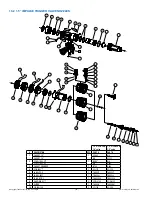
10.2 1.5” IMPULSE TRIGGER VALVE NOZZLES
10.3 1” G-FORCE NOZZLE
11.0 MAINTENANCE
11.1 FIELD LUBRICATION
11.2 IMPULSE TRIGGER VALVE LUBRICATION
11.3 SERVICE TESTING
112.3.1 HYDROSTATIC TESTING
11.3.2 FLOW TESTING
11.3.3 RECORDS
11.4 REPAIR
12.0 WARRANTY
13.0 OPERATION AND INSPECTION CHECKLIST
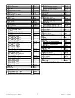
Table Of Contents


