17
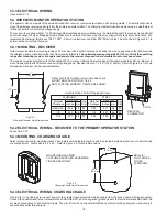
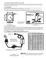
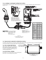
5.5 JOYSTICK MONITOR OPERATOR STATION
5.5.1 MOUNTING
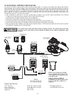
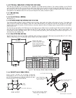
This operator station allows the monitor to be controlled by a joystick. The installer will need to mount the joystick and connect the
cables to the communication interface box or to a primary operator station. The joystick needs to be mounted in a weatherproof
location. Example: Inside the cab of the truck.
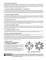
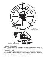
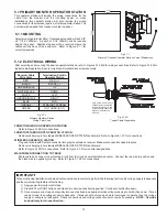
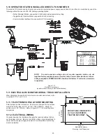
Select proper weatherproof operating location. Joystick will require 4 ½” x 4 ½” (114 x 114mm) of panel space. A depth of 4”
(100mm) will be required behind the panel. Refer to Figure 5.5.1.1 for hole dimensions.
After mounting, the installer may rotate the joystick up to 22 degrees in either direction. To rotate joystick, lift the rubber boot to
expose adjustable clamp. Loosen the clamping screws, rotate the joystick to desired position, and tighten clamping screws.
Fig 5.5.1.1
Joystick Operator Station
Hole Dimensions
Fig 5.5.1.2
Joystick Instruction Label
2-27/32
(72 mm)
2-27/32
(72 mm)
1/4 (6 mm)
3 (76 mm)
2
(51
mm)
HOLE MOUNTING DETAIL
®
TASK FORCE TIPS
FIRE FIGHTING EQUIPM
ENT
www.tft.com
FOG
STRAIGHT
SMART SHAPER
1)
2)
NOZZLE STOPS AT FULL FOG
PRESS AGAIN FOR FLUSH
®
TASK FORCE TIPS
FIRE FIGHTING EQUIPMENT
STRAIGHT
STREAM
AUX
FUNCTION
TRIGGER
FOG THEN FLUSH
800-348-2686 • www.tft.com
Y5336
Install joystick instruction
label nearby for quick
operation reference.
5.5.2 ELECTRICAL WIRING
The joystick operator station must be connected to the included Y4E-COMM Communication Interface Box or a separately supplied
Y4E-RP Primary Operator Station. By connecting the joystick to a communication interface box, a primary operator station is not
required and the installer has the option to enable the joystick operator station with the master override feature (see Section 6.2.2).
When a pump panel operator station is being installed, the installer can connect the joystick to the Primary Operator Station, which
will eliminate the need to install the communication interface box.
5.5.2.1 WIRING TO A COMMUNICATION INTERFACE BOX
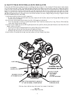
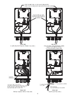
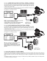
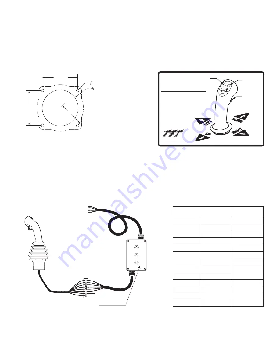
The joystick cables will be connected to the factory supplied 10' cable from the Communication Interface Box. See figure 5.5.2.1.
Fig 5.5.2.1
Joystick Operator Station Wiring
to Communication Interface Box
Do not connect 12VDC to Communication Interface Box
wires if configured for GROUND inputs. This will result in
damage to the communication board. See section 5.7.3.
NOTE
STREAM
FOG
TRIGGER
n/u
n/u
n/u
n/u
n/u
Blue
Green
Orange
White
Brown
Black
Purple
Yellow
ORANGE
GREEN
Water Valve**
n/u
n/u
n/u
n/u
n/u
UP
DOWN
LEFT
RIGHT
COMMON
Grey
Black/White
Tan
Pink
Red
WHITE
BLUE
YELLOW
BROWN
N/A
Joystick
Cable Color
Function
Interface Box
Cable Color
Y4E-COMM COMMUNICATION INTERFACE BOX
- FACTORY CONFIGURED FOR VOLTAGE INPUTS
- TO CONFIGURE FOR GROUND INPUTS, SEE SEC 5.7.3
**WATER VALVE CONNECTION **
-TRIGGER ACTUATION SWITCHES
ORANGE WIRE TO +12/24 VDC
- 5 AMP SWITCH CONTACT RATING
- WHEN SWITCHING A RELAY OR SOLENOID,
INSTALL A SUPPRESSION DIODE
POWER AND
COMMUNICATION CABLE
SEE SECTION 5.7.2
INSTALLER SUPPLIED
TERMINAL BLOCK OR SPLICES
+12/24 VDC

