background image

©Copyright Task Force Tips, Inc. 2016-2017 

LIA-540 September 25, 2017 Rev03

3

1.0  MEANING OF SAFETY SIGNAL WORDS

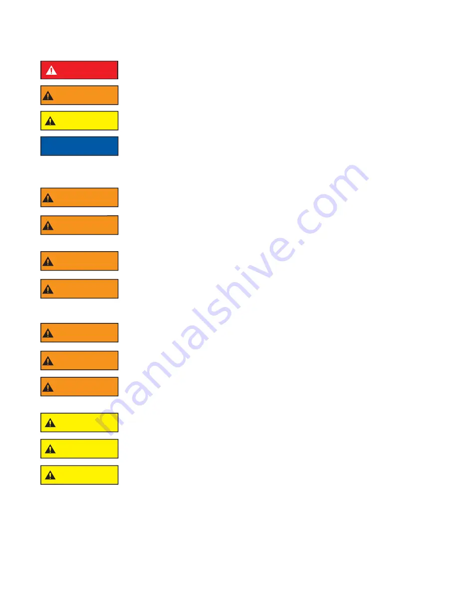
A safety related message is identifi ed by a safety alert symbol and a signal word to indicate the level of risk involved with a particular 
hazard. Per ANSI standard Z535.6-2006, the defi nitions of the four signal words are as follows:

DANGER

DANGER indicates a hazardous situation which, if not avoided, will result in death or serious 
injury.

WARNING

WARNING indicates a hazardous situation which, if not avoided, could result in death or serious 
injury.

CAUTION

CAUTION indicates a potentially hazardous situation which, if not avoided, may result in minor 
or moderate injury.

NOTICE

NOTICE is used to address practices not related to personal injury.

2.0 SAFETY

WARNING

Quick changes in valve position can cause high pressure spikes due to water hammer and may 
result in damaged equipment which could lead to injury or death.  Open and close the valve 
slowly to avoid water hammer.

WARNING

The  Pressure  Relief  Valve  will  open  to  relieve  excess  pressure  but  it  may  not  have  enough 
fl ow capacity to protect against large pressure spikes such as those caused by water hammer. 
Excess pressure can cause equipment failure and directly or indirectly lead to injury or death. 
Always operate valves slowly to avoid the risk of water hammer.

WARNING

Injury or death can result from burst hoses and fi ttings.  Be sure the pressure relief valve is set 
at the proper pressure for the type of hose and equipment you are using.  See NFPA 1961 and 
NFPA 1962.

WARNING

Injury or death may occur by attempting to use a damaged valve.  Per NPFA 1962, the device 
shall be inspected and tested at least quarterly.  Before use, inspect for damage resulting from:
     • Failure to drain valve followed by exposure to freezing conditions
     • Exposure to temperatures in excess of 160 degrees F
     • Missing parts, physical abuse

WARNING

This  equipment  is  intended  for  use  by  trained  personnel  for  fi refi ghting.    Its  use  for  other 
purposes may involve hazards not addressed by this manual.  Seek appropriate guidance and 
training to reduce risk of injury.

WARNING

Kinks in supply hose may reduce water fl ow and cause injury or death to persons dependant on 
water fl ow.  Avoid tight bends to minimize risk of hoseline kinks.  

WARNING

The valve may be damaged if frozen while containing signifi cant amounts of water. Such damage 
may to diffi

  cult to detect visually and can lead to possible injury or death. Any time the valve 

is  subject  to  possible  damage  due  to  freezing,  it  must  be  hydrostatically  tested  by  qualifi ed 
personnel before being considered safe for use.

CAUTION

 Maximum operating pressure 300 psi (21 bar).  Do not exceed 300 psi (21 bar) on either side of 
the valve.

CAUTION

Valve must be properly connected. Mismatched or damaged connectors may cause leaking or 
uncoupling under pressure and could cause injury.

CAUTION

Use with salt water is permissible provided the LDH Gated Wye is thoroughly cleaned with fresh 
water after each use. The service life of the LDH Gated Wye  may be shortened due to the eff ects 
of corrosion and is not covered under warranty.

Summary of Contents for LDH GATED WYE

Page 1: ...rom http tft com Call 800 348 2686 with any questions WARNING This instruction manual is intended to familiarize firefighters and maintenance personnel with the operation servicing and safety procedures associated with the LDH Gated Wye NOTICE This manual should be kept available to all operating and maintenance personnel OPERATING RANGE Pressure Max 300 PSI Pressure Min Full Vac Hydrostatic Proof T...

Page 2: ...l skill level required to operate any equipment you may be called upon to use 5 It is your responsibility to know that your equipment is in operable condition and has been maintained in accordance with the manufacturer s instructions 6 Failure to follow these guidelines may result in death burns or other severe injury FEMSA Fire and Emergency Manufacturers and Service Association P O Box 147 Lynnfi...

Page 3: ...roper pressure for the type of hose and equipment you are using See NFPA 1961 and NFPA 1962 WARNING Injury or death may occur by attempting to use a damaged valve Per NPFA 1962 the device shall be inspected and tested at least quarterly Before use inspect for damage resulting from Failure to drain valve followed by exposure to freezing conditions Exposure to temperatures in excess of 160 degrees F...

Page 4: ...rating Pressure 300 psi 20 bar Hydrostatic Proof Test Pressure 900 psi 62 bar Temperature Rating 25 F to 135 F 32 C to 57 C For temperatures below 32 F 0 C valves must be drained after use to avoid damage See section 2 0 SAFTEY 3 3 CORROSION Hose couplings are attached using polymer bearing rings which provide electrical insulation to help galvanic corrosion The parts are then hard anodized and fin...

Page 5: ...ion indicator says OPEN To close the valve turn the valve crank the opposite way until the valve position indicator says CLOSED 5 2 AIR VENT AND WATER DRAIN This device is equipped with an air vent drain which will allow the air to escape from the valve when the inlet is charged The air vent drain is opened by turning the knob counter clockwise and closed by turning it clockwise To drain the water...

Page 6: ...ast quarterly for proper function per NFPA 1962 Section 8 2 or as water quality and use may require Moving parts such as handles valve ball and couplings should be checked for smooth and free operation Seals shall be greased as needed with silicone based grease such as Dow Corning 112 Any scrapes that expose bare aluminum should be cleaned and touched up with enamel paint such as Rust Oleum In par...

Page 7: ...1 VFHB4MX2F 6 3 8 16 X 1 75 SOCKET SCREW 1 VT37 16SH1 7 7 GEARBOX SUBASSEMBLY 1 A1633 GEARBOX SUBASSEMBLY 1 A1633R 8 O RING 128 2 VO 128 9 DRAIN VALVE 1 A1621 10 HALF BALL 2 A1043A ITEM DESCRIPTION QTY PART 11 SEAL 2 A1520 12 MATE 2 A201 13 1 4 20 X 1 2 SET SCREW 3 VT25 20SS500 14 O RING 115 2 VO 115 15 BUSHING FOR ALUM HALF BALL 2 A2095 16 TRUNNION 2 AY357 17 FOOT 4 A2037 18 O RING 150 1 VO 150 1...

Page 8: ... Copyright Task Force Tips Inc 2016 2017 LIA 540 September 25 2017 Rev03 8 7 2 PARALLEL SHAFT GEARBOX 12 11 20 19 18 17 16 15 14 13 10 9 8 7 6 5 4 3 2 1 21 22 23 24 25 26 27 28 29 ...

Page 9: ...11 NYLON BUSHING 1 AY307 12 GEAR BUSHING 1 A1548 13 DOUBLE GEAR 1 A1554 14 BUSHING 1 A1549 15 INNER TRUNNION 1 A1553 INNER TRUNNION 1 A1553R 16 DOWEL PIN 2 VP312X 50 17 O RING 154 1 VO 154 18 SUBPLATE 1 A1551 19 O RING 028 1 VO 028 20 INNER BUSHING 1 A1552 21 FOLDING HANDLE LABEL 1 AY342 22 10 24 X 3 8 BUTTON HEAD SCREW 1 VT10 24BH500 23 WASHER 1 VW500X203 60 24 POSITION INDICATOR 1 A1558 25 NAME ...

Page 10: ... A1294 1 NFS RING A4561 A4576 1 O RING VO 248 VO 254 1 MATE PSM4 25 X PSF5 25 A4730 1 CUP SEAL A1596 1 PORT COVER A1298 1 PLASTIC STRIP A1291 7 5 SIDE B DUAL SIDE COMPONENTS QTY DESCRIPTION 4 0 STORZ 5 0 STORZ 6 0 STORZ 4 0 MALE 4 5 MALE 5 0 MALE 6 0 MALE 1 OUTLET MATE A2015 A2016 A2016 A2016 A2016 A2016 A2016 1 CUP SEAL A1597 A1596 A1596 A1596 A1596 A1596 A1596 1 PLASTIC STRIP A1292 A1291 A1291 A...

Page 11: ...has been misused or neglected including failure to provide reasonable maintenance or if there have been accidents to the equipment or if it has been repaired or altered by someone else THIS IS A LIMITED EXPRESS WARRANTY ONLY TFT EXPRESSLY DISCLAIMS WITH RESPECT TO THE EQUIPMENT ALL IMPLIED WARRANTIES OF MERCHANTABILITYANDALL IMPLIED WARRANTIES OF FITNESS FORAPARTICULAR PURPOSE THERE IS NO WARRANTY...

Page 12: ...ached BEFORE BEING PLACED BACK IN SERVICE appliances must be inspected to this checklist 1 All valves open and close smoothly and fully 2 The waterway is clear of obstructions 3 There is no damage to any thread or other type connection 4 The pressure setting of the relief valve if any is set correctly 5 All locks and hold down devices work properly 6 Internal gaskets are in accordance with NFPA 19...

Reviews: