background image

0

0

10

10

20

20

30

40

50

60

70

80

0

0

20

10

40

20

60

30

80

40

100

50

120

60

140

70

160

80

90

180 200 220 240 260 280 300

HORIZONTAL DISTANCE (FEET)

VERTICAL

DIST

ANCE

(FEET)

METERS

METERS

A

B

C

D

E

MASTER, 100 PSI (7 BAR, 700 KPA )

8

Step 3: Calculate flow with automatic nozzle.

Using the pressure loss constant from step 2 and the following equation, the flow with an automatic nozzle can be

calculated for your particular installation.

Where:

automatic nozzle flow in GPM (or LPM)

nominal nozzle operating pressure in PSI (or BAR)

Mount a graph or table of the results adjacent to the in-line pressure gauge. Deliver any desired flow by adjustment of

pump pressure.

Q

P

auto

auto

Q

= (P

- P )C

auto

in-line

auto

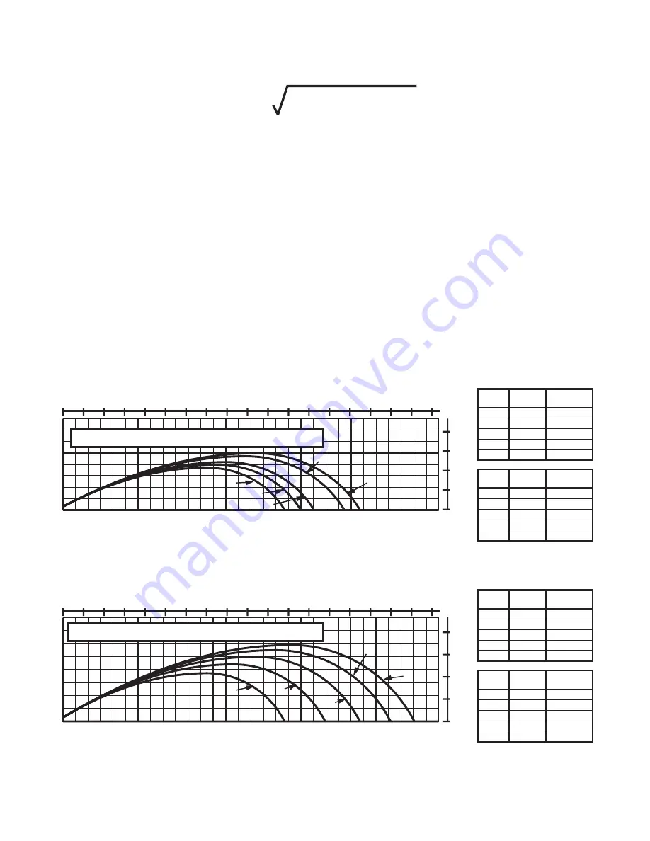
Figures 4A and 4B give the stream trajectory for the Master, Monsoon and Typhoon nozzles at various flows.

Notes on trajectory graphs:

• Graphs show approximate effective stream trajectory at 30 degrees elevation in no wind

conditions. Distance to last water drops approximately 10% farther.

• Trajectories shown are for water. The addition of foam is expected to decrease the reach by 10%.
• Tail or head winds of 20 MPH (30 KPH) may increase or decrease the range approximately 30%.
• Stream trajectory of Typhoon based on "The Trajectories of Large Fire Fighting Jets" by A.P. Hatton

and M.J. Osborne, Reference: "The International Journal of Heat and Fluid Flow", Vol 1 No 1.

3.4 STREAM TRAJECTORY DATA

FIG 4A - Master and Monsoon Stream Trajectory

CURVE

A
B
C
D
E

CURVE

A
B
C
D
E

GPM

FLOW

300
400
500
800

1000

LPM

FLOW

1100
1500
1900
3000
3800

LBS

REACTION

150
200
260
400
510

KGF

REACTION

70
90

120
180
230

CURVE

A
B
C
D
E

CURVE

A
B
C
D
E

GPM

FLOW

300
600

1000
1500
2000

LPM

FLOW

1100
2300
3800
5700
7500

LBS

REACTION

160
300
510
760

1000

KGF

REACTION

70

140
230
340
450

0

10

20

30

40

50

60

70

80

90

METERS

0

10

20

METERS

0

10

20

30

40

50

60

70

80

0

20

40

60

80

100 120 140 160 180 200 220 240 260 280 300

HORIZONTAL DISTANCE (FEET)

A

B

C

D

E

MONSOON, 100 PSI (7 BAR, 700 KPA)

VERTICAL

DIST

ANCE

(FEET)

EXCEL\MISC\RAN_MON

EXCEL\MISC\RANMAST

LIM-030 November 22, 1999 Rev 1

©Copyright Task Force Tips, Inc. 1999

Summary of Contents for MASTER

Page 1: ...g and safety procedures associated with the Master Monsoon and Typhoon firefighting nozzles This manual should be kept available to all operating and maintenance personnel INSTRUCTIONS FOR SAFE OPERAT...

Page 2: ...1 0 MEANING OF SIGNAL WORDS A safety related message is identified by a safety alert symbol and a signal word to indicate the level of risk involved with a particular hazard Per ANSI standard Z535 4...

Page 3: ...nstalling the nozzle 2 0 GENERAL INFORMATION Do not couple aluminum to brass Dissimilar metals coupled together can cause galvanic corrosion that can result in inability to unscrew threads or complete...

Page 4: ...ils FIG 1 Methods for Moving Stream Shaper TASK FORCE TIPS TASK FORCE TIPS TASK FORCE TIPS TASK FORCE TIPS TASK FORCE TIPS TASK FORCE TIPS TASK FORCE TIPS TASK FORCE TIPS Fig 1A Stream Shaper moved ma...

Page 5: ...zzles with electric stream shaper actuation are shipped with a wiring diagram TFT item LIM 040 Other documentation is available on request The actuator is not rated as ignition proof explosion proof o...

Page 6: ...ischarge opening to maintain a constant pressure throughout the flow range of the nozzle For example when the pressure at the inlet increases the exit area is automatically increased until the inlet p...

Page 7: ...nozzle Step 2 Find pressure loss constant Flow water with a smooth bore nozzle and record the nozzle s size pitot pressure and in line pressure gauge reading The smooth bore nozzle s flow is calculate...

Page 8: ...last water drops approximately 10 farther Trajectories shown are for water The addition of foam is expected to decrease the reach by 10 Tail or head winds of 20 MPH 30 KPH may increase or decrease th...

Page 9: ...rajectory VERTICAL DISTANCE FEET 0 10 20 30 METERS 0 20 40 80 METERS 0 10 20 30 40 50 60 70 80 90 100 0 40 80 120 160 200 240 280 320 360 400 HORIZONTAL DISTANCE FEET A B C D E TYPHOON 120 PSI 8 3 BAR...

Page 10: ...til push rod clears shaft The cylinder and piston will come out as a unit Remove the small spring and stainless steel poppet from the center of the shaft Remove debris Reassemble the nozzle Figures 5A...

Page 11: ...nd Parts CYLINDER PISTON RETURN SPRING CONTROL POPPET SPRING LUBE LUBE LUBE LUBE SHAFT tft typhoon mt850 tft monsoon ms_front RETURN SPRING CYLINDER SHAFT POPPET SPRING CONTROL LUBE LUBE LUBE LUBE PIS...

Page 12: ...who is an intended or unintended beneficiary of the equipment shall not be entitled to recover from TFT any consequential or incidental damages for injury to person and or property resulting from any...

Reviews: