PF-770
Check & Recovery for Slating of TRAY PAPER
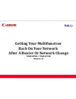
<Checking Procedure>
1. Remove the STOPPER DECK.
2. Check the right and left slanting
condition of the TRAY PAPER surface.
<Checking method>
Turn the SHAFT LIFT and adjust the top
part of STAY DECK SIDE becomes the
same flat surface level with the TRAY PAPER
at the FEED UNIT side.
In that height position, check that the TRAY PAPER surface of the opposite FEED UNIT side is lower than
the STAY DECK SIDE top part. In addition, the height of STAY DECK SIDE is the same height at the
FEED UNIT side and opposite FEED UNIT side.
1) If the opposite FEED UNIT side is lower than the FEED UNIT side
・・・・
OK
3. Check there is not slanting between the front and rear of the TRAY PAPER.
<Checking method>
Turn the SHAFT LIFT and when the top surface of the TRAY
PAPER is aligned with the convex part of FRAME DECK
REAR and FRAME F L,
1)Same flat height level at front and rear
OK
2)If it has about 5mm difference height between front and rear
NG
STOPPER DECK
Clearance
(about 5mm)
SHAFT LIFT
STAY DECK SIDE
Same flat level
FEED UNIT side
TRAY PAPER
Feeding direction
FEED UNIT side
STAY DECK SIDE
Opposite FEED UNIT side
TRAY PAPER
FRAME F L
FRAME DECK REAR
TRAY PAPER
Same height at front
/ rear
OK
About 5mm
About 5mm difference between
front and rear height
NG
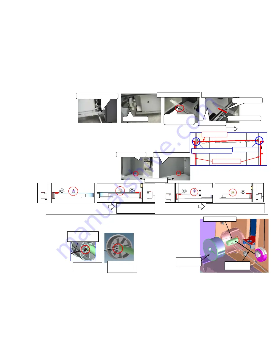
<Recovery Procedure>
If above item 2 and 3 is NG, the following re-assembling is necessary.
At checking of above item 3, if the TRAY PAPER lower side is not
normal, it has a possibility that the
ball is out of position as shown in
the NG figure, re-assembly of the
wire is necessary.
In the case of NG above item 2, it
has a possibility that the ball is out
of position at both of front and rear,
re-assembly of an front and rear
wire is necessary.
OK
: A ball terminal
goes into the hole
of shaft.
NG
: A ball terminal
is out of shaft.
Black color
WIRE
* As shown in the right figure, make
it a ball terminal go into the hole of
SHAFT within PULLEY LIFT WIRE
DRUM at the time of re-assembly.
Be cautions especially at the time of
the assembly of a black wire.
SHAFT LIFT ASSY
WIRE LIFT L
black color
PULLEY LIFT
WIRE DRUM
Opposite FEED UNIT side
34
Summary of Contents for 6500i
Page 48: ... The film attached procedure J49XX J50XX J51XX J600X 3 9 48 ...
Page 52: ... Replacement procedure for the bushing J49XX J50XX J51XX J600X 7 9 52 ...
Page 57: ... The film attached procedure J6100 J6110 DF 3 6 57 ...
Page 71: ... The film attached procedure Corner Folding 3 6 71 ...
Page 73: ...Corner Folding 5 6 73 ...
Page 74: ...Corner Folding 6 6 74 ...
Page 103: ...Abnormal sound from the fuser section 3 5 For 3500i 4500i 5500i 103 ...
Page 104: ...Abnormal sound from the fuser section 4 5 For 3500i 4500i 5500i 104 ...