GTS
Technical Manual
9. April 2021
Edition: V1.00/2021
6-26
Copyright © 2020, Diversey
06
.2
2.
19
h
al
l s
en
so
rs
-
s
te
er
in
g
an
gl
e
-
35
00
µi
cr
o_
V1
.0
0.
fm
6.5
Hall sensor
6.5.3
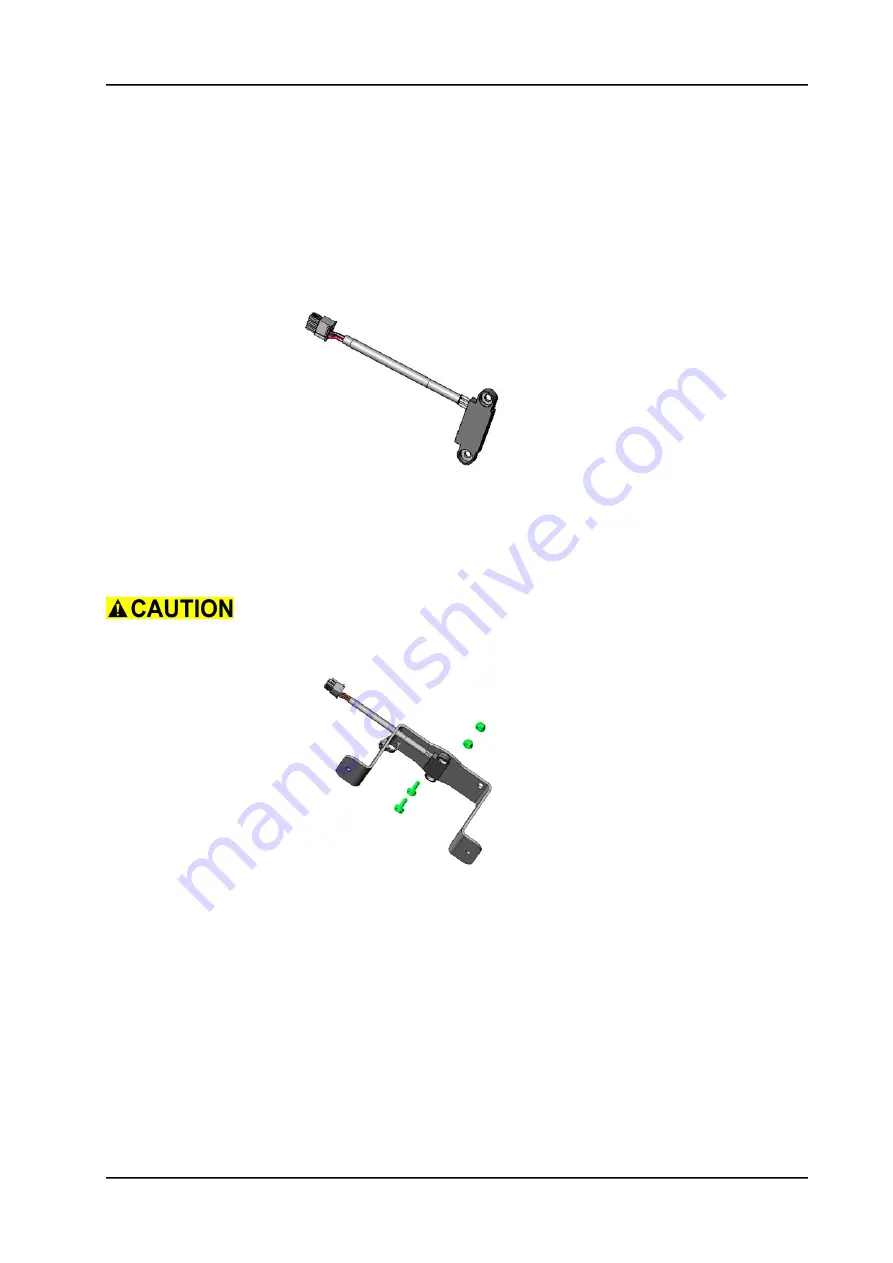
Mounting of hall sensor steering angle
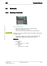
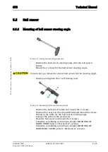
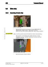
Picture 21: Hall sensor steering angle unit
•
Position the hall sensor steering angle onto the hall sensor
holder.
•
Mount the 2 screws for the hall sensor steering angle.
Ensure that you mount the correct hall sensor for the steering angle.
•
Position and tighten the 2 self-locking nuts.
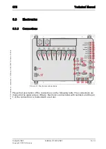
Picture 22: Mounting hall sensor steering angle
•
Position the hall sensor holder and mount the 2 screws.
•
Position the covers on the LH and RH side and mount the screws.
•
Thread in the cable for the hall sensor steering angle.
•
Connect the cable to the electronics.
•
Place the foot cover and mount the 2 screws.
•
Complete assembling according to chapter MOUNTING OF
FRONT HOOD (refer to “Mechanical” section).
•
Complete assembling according to chapter MOUNTING OF
DRIVER SEAT COVER (refer to “Mechanical” section).
Summary of Contents for AERO 3500 micro
Page 1: ...Edition V1 00 2021 Technical Manual ...
Page 5: ...9 April 2021 Edition V1 00 2021 Copyright 2020 Diversey Technical Manual 1 Forward ...
Page 8: ...9 April 2021 Edition V1 00 2021 Copyright 2020 Diversey Technical Manual 2 Elementary ...
Page 11: ...9 April 2021 Edition V1 00 2021 Copyright 2020 Diversey Technical Manual 3 General ...
Page 15: ...9 April 2021 Edition V1 00 2021 Copyright 2020 Diversey Technical Manual 4 Technical data ...
Page 24: ...9 April 2021 Edition V1 00 2021 Copyright 2020 Diversey Technical Manual 5 Mechanical ...
Page 96: ...9 April 2021 Edition V1 00 2021 Copyright 2020 Diversey Technical Manual 6 Electrical ...
Page 145: ...9 April 2021 Edition V1 00 2021 Copyright 2020 Diversey Technical Manual 8 Revision ...
Page 147: ...9 April 2021 Edition V1 00 2021 Copyright 2020 Diversey Technical Manual 9 Appendix ...

