GTS
Technical Manual
9. April 2021
Edition: V1.00/2021
5-31
Copyright © 2020, Diversey
05
.3
0.
23
to
ol
lo
w
er
in
g
un
it
-
to
ol
lo
w
er
in
g
un
it
-
35
00
µi
cr
o_
V1
.0
0.
fm
5.6
Tool lowering unit
5.6.1
Removing of tool lowering unit
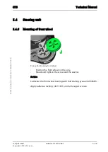
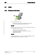
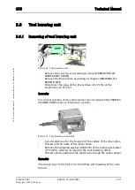
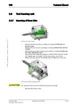
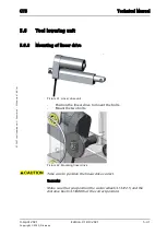
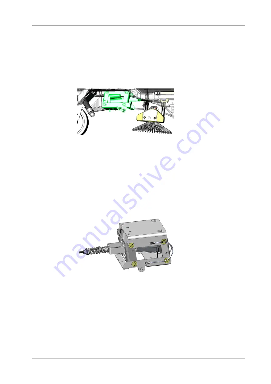
Picture 44: Tool lowering unit
•
Remove the seat cover according to chapter REMOVING OF
DRIVER SEAT COVER.
•
Remove the brush drive according to chapter REMOVING OF
BRUSH DRIVE.
•
Disconnect the plug of the linear drive (4127185) at the
electronics (4131532).
Remarks
For correct position of the connections refer to chapter ELECTRONICS
CONNECTIONS (refer to “Electrical” section).
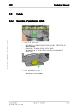
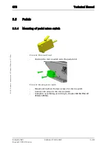
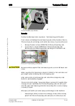
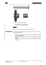
Picture 45: Tool lowering unit details
•
Cut all cable ties for the fixation of the cables of the liner drive.
•
Thread out the cable of the linear drive.
•
Remove the retaining washer (4058370) of the metal rope holder
(4134070), which is located on the tool lowering offset.
•
Thread out the ending of the metal rope trough the castor wheel.
Remarks
The metal rope (4134183) is for the lifting and lowering of the side
broom.
Summary of Contents for AERO 3500 micro
Page 1: ...Edition V1 00 2021 Technical Manual ...
Page 5: ...9 April 2021 Edition V1 00 2021 Copyright 2020 Diversey Technical Manual 1 Forward ...
Page 8: ...9 April 2021 Edition V1 00 2021 Copyright 2020 Diversey Technical Manual 2 Elementary ...
Page 11: ...9 April 2021 Edition V1 00 2021 Copyright 2020 Diversey Technical Manual 3 General ...
Page 15: ...9 April 2021 Edition V1 00 2021 Copyright 2020 Diversey Technical Manual 4 Technical data ...
Page 24: ...9 April 2021 Edition V1 00 2021 Copyright 2020 Diversey Technical Manual 5 Mechanical ...
Page 96: ...9 April 2021 Edition V1 00 2021 Copyright 2020 Diversey Technical Manual 6 Electrical ...
Page 145: ...9 April 2021 Edition V1 00 2021 Copyright 2020 Diversey Technical Manual 8 Revision ...
Page 147: ...9 April 2021 Edition V1 00 2021 Copyright 2020 Diversey Technical Manual 9 Appendix ...

