GTS
Technical Manual
19. April 2010
Edition: V1.00/2010
5-25
Copyright © 2010, Diversey Inc.
05.0 s
w
in
go 1255 B Power - me
ch
anics
.fm
Remarks
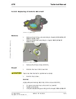
To pull out the bolt, you need to thread in a screw into the bolt.
Dimensions: M6, min. length 30mm.
•
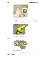
Remove the foot lever (06/102)
Mount
•
Build in new foot lever.
•
Position the bolt for the foot lever fixation.
•
Insert the stop pin.
•
Position the axle into the pusher rack.
•
Mount the retaining ring.
•
Position the microswitch.
•
Mount screw for microswitch and adjust accordingly.
Adjustment
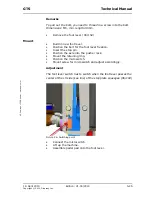
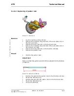
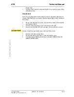
The foot lever switch has to switch when the foot lever passes the
center of the LH side (see line) of the stop plate squeegee (06/104)
Picture 26: Switching point
•
Connect the microswitch.
•
Lift up the machine.
•
Assemble pedal pad onto the foot lever.
Summary of Contents for swingo 1255B Power
Page 1: ...Edition V1 00 2010 Technical Manual ...
Page 4: ...19 April 2010 Edition V1 00 2010 Copyright 2010 Diversey Inc Technical Manual 1 Foreword ...
Page 7: ...19 April 2010 Edition V1 00 2010 Copyright 2010 Diversey Inc Technical Manual 2 Elementary ...
Page 10: ...19 April 2010 Edition V1 00 2010 Copyright 2010 Diversey Inc Technical Manual 3 General ...
Page 22: ...19 April 2010 Edition V1 00 2010 Copyright 2010 Diversey Inc Technical Manual 5 Mechanical ...
Page 59: ...19 April 2010 Edition V1 00 2010 Copyright 2010 Diversey Inc Technical Manual 6 Electrical ...
Page 80: ...19 April 2010 Edition V1 00 2010 Copyright 2010 Diversey Inc Technical Manual 8 Revision ...
Page 82: ...19 April 2010 Edition V1 00 2010 Copyright 2010 Diversey Inc Technical Manual 9 Appendix ...
Page 85: ...19 April 2010 Edition V1 00 2010 Copyright 2010 Diversey Inc Technical Manual 10 Notes ...

