GTS
Technical Manual
19. April 2010
Edition: V1.00/2010
5-29
Copyright © 2010, Diversey Inc.
05.0 s
w
in
go 1255 B Power - me
ch
anics
.fm
•
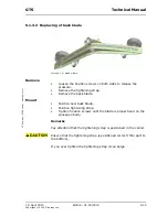
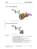
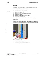
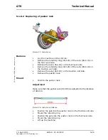
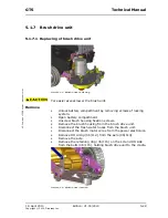
Push bolts inwards to release the brush unit.
Make sure that you hold the brush drive unit firmly.
•
Pivot the complete brush drive unit out.
Mount
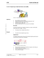
On EBU models the brush unit fixation bolts are different in length.
Therefore the small bolt (06/115) is mounted on the LH and the
longer bolt (06/121) on the RH side.
•
Position the brush drive unit onto the cradles.
•
Position the bolts and mount the retaining ring (06/110) on
the LH and the RH side.
•
Position the axle (06/114) and mount the circlip (06/112).
•
Connect the brush motor wires to the power electronics.
•
Connect the fresh water hoses to the brush drive unit.
•
Position the brush housing on the brush drive unit.
•
Position the brush housing fixation screws and tighten them.
•
Close and lock the battery compartment on both sides with the
screws of the locking system.
Adjustment
•
M5 (04/125) with 5 Nm
•
Brush minus
•
M6 (04/128) with 7 Nm
•
Brush plus
Summary of Contents for swingo 1255B Power
Page 1: ...Edition V1 00 2010 Technical Manual ...
Page 4: ...19 April 2010 Edition V1 00 2010 Copyright 2010 Diversey Inc Technical Manual 1 Foreword ...
Page 7: ...19 April 2010 Edition V1 00 2010 Copyright 2010 Diversey Inc Technical Manual 2 Elementary ...
Page 10: ...19 April 2010 Edition V1 00 2010 Copyright 2010 Diversey Inc Technical Manual 3 General ...
Page 22: ...19 April 2010 Edition V1 00 2010 Copyright 2010 Diversey Inc Technical Manual 5 Mechanical ...
Page 59: ...19 April 2010 Edition V1 00 2010 Copyright 2010 Diversey Inc Technical Manual 6 Electrical ...
Page 80: ...19 April 2010 Edition V1 00 2010 Copyright 2010 Diversey Inc Technical Manual 8 Revision ...
Page 82: ...19 April 2010 Edition V1 00 2010 Copyright 2010 Diversey Inc Technical Manual 9 Appendix ...
Page 85: ...19 April 2010 Edition V1 00 2010 Copyright 2010 Diversey Inc Technical Manual 10 Notes ...

